Thanks for that link.Thanks for the links. I was also thinking something along the lines of this one by EUVL:
http://www.diyaudio.com/forums/solid-state/298026-tin-fets-headphone-amplifier-2.html
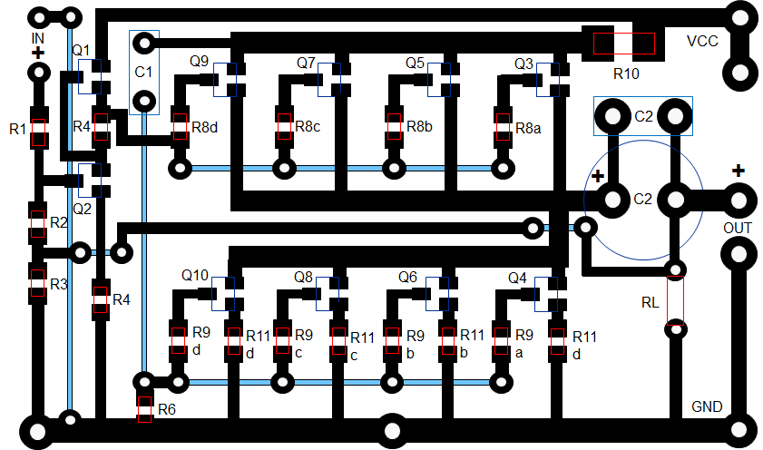
The easphyx and EUVL circuits are a little different as they are White followers and come with even lower Zout and some feedback.
Maybe something like this? 39mm x 64mm:
I built the BF862 white follower HA and am having problems getting any sound out of it. I think the Idss of my 862's is so high (20 to 23mA) it will take revision of the resistor values (similar to what I did on Juma's) to get it to balance.
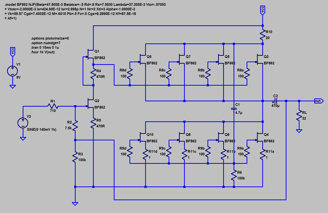
For reference, here is schematic from EUVL's Spice file that Mark Johnson provided:
With a 12v supply, I am getting 0.809v across R5, 9.3v at the Source of Q1 (voltage going to Gate of outputs), Vdc at upstream of C2 is 9.05v. Total current flow is measured as 2,12v acrosss 23.5R at R10. Current through all lower outputs seems to be maxed at 20mA to 23mA.
I tried changing R4 and R5 (same time) to 1500R, 470R, 220R, 100R and nothing worked.
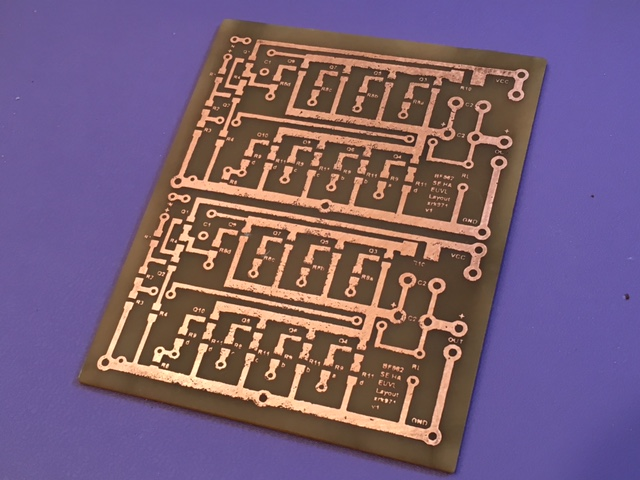
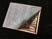
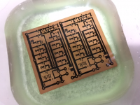
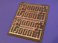
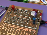
Iron on transfer:

Etching:

Waiting for drilling:
Build completed:
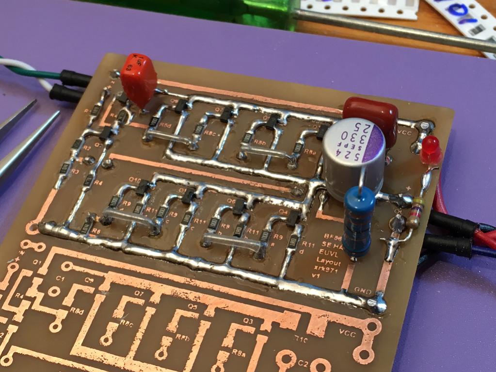
I am using 330uF Panasonic OSCON for C2 with 1uF 230v MKT bypass, C1 is shown 1uF 63v but later switched for 10uF electrolytic and still did not work.
Any sugestions?
Attachments
Last edited:
The sch shows ~12V across each of the sot23
20mA is too much since it gives ~240mW dissipation before you apply any signal.
10mA would be a better target for each sot23.
The Source resistor in the lower jFETs sets the current that passes.
change from 1r0 to 2r2 and measure again.
If it's still too high try 3r3.
Philip's spec these @ 225mW max in 1999
NXP's spec @ 300mW in 2005
Last edited:
I built the BF862 white follower HA and am having problems getting any sound out of it. I think the Idss of my 862's is so high (20 to 23mA) it will take revision of the resistor values (similar to what I did on Juma's) to get it to balance.
(...)
Any sugestions?
Try to learn LTSPICE.
With EUVL already providing the modelled circuit it is so nice to play around before shedding solder.
You can generate a model for higher Idss BF862 like this.
Then see what 12V in supply does to the circuit.
I swiftly plugged in devices with Idss of 23mA and used 12V and find that the circuit should still work.
LTSpice even tells you that the lower JFETs dissipate 140mW, each, as they only see half of the 12V.
The top JFETS have even less.
I might start another "Easy Peasy" etching your own PCB's with household materials.
Use laser printer to make transfers onto special paper. Iron on transfer to copper. Etch with muriatic acid and peroxide (or vinegar but slower).
What kind of special paper and where do you purchase it?
Many are reporting that glossy magazine paper is best.What kind of special paper and where do you purchase it?
I can't get any paper type to work well from my Brother laser printer.
I bought the recommended inkjet photo paper and it was pretty poor.
Try to learn LTSPICE.
With EUVL already providing the modelled circuit it is so nice to play around before shedding solder.
You can generate a model for higher Idss BF862 like this.
Then see what 12V in supply does to the circuit.
I swiftly plugged in devices with Idss of 23mA and used 12V and find that the circuit should still work.
LTSpice even tells you that the lower JFETs dissipate 140mW, each, as they only see half of the 12V.
The top JFETS have even less.
I do use TINA but need to learn LTSpice as models are more readily available. I do notice that bottom ones get hotter, but imagine it feels like they saturated so no room to make music.
What kind of special paper and where do you purchase it?
It's not paper at all. It is vinyl self adhesive shelving liner. Stick it to bond paper as backing then laserprint of photocopy design onto the smooth vinyl surface by sending both through machine. This particular brand goes through printer/copier fine and doesn't melt. It releases almost 100% of the toner onto the copper when heated with hot iron.
https://www.dollartree.com/Con-Tact...dhesive-Shelf-Liners-18x54-/p306003/index.pro
Last edited:
The sch shows ~12V across each of the sot23
20mA is too much since it gives ~240mW dissipation before you apply any signal.
10mA would be a better target for each sot23.
The Source resistor in the lower jFETs sets the current that passes.
change from 1r0 to 2r2 and measure again.
If it's still too high try 3r3.
Philip's spec these @ 225mW max in 1999
NXP's spec @ 300mW in 2005
Ok, I will play with the source resistors on the bottom half. I am guessing 3R3 will probably be what it takes to make this low enough.
Thanks.
I have a stupid question - in the schematic, Rl represents the 32ohm headphone, not a load resistor in parallel with output to headphone right? I mistakenly put a 33R resistor on PCB and of course that sucks all the power from any headphone that is also plugged in. It wasn't until I put a DVM in volts AC on output that I see it playing music. But no sound from headphones. So delete RL right?
I had to change source resistors to 47R before I could get 10 to 12mA bias current in ea leg. Total bias is now 40 to 48mA. DC voltage upstream of blocking cap is rather high 10v rather than 7v (14v supply voltage now).
Looks like getting close to working though.
I had to change source resistors to 47R before I could get 10 to 12mA bias current in ea leg. Total bias is now 40 to 48mA. DC voltage upstream of blocking cap is rather high 10v rather than 7v (14v supply voltage now).
Looks like getting close to working though.
Last edited:
This is going to sound a bit 'retro' but could you add some donuts for the SMD resistors so that those of use that are more comfortable with thru hole can just fit 'normal' resistor vertically
I'd leave the Rl there but call it an optional load resistor Rp, for example) for experimenters to play with
I'd leave the Rl there but call it an optional load resistor Rp, for example) for experimenters to play with
Very strange. I removed RL. I plugged 60R headphones in and when source is on I see volts at output fluctuate 0.4v to 1v and 0.0v when source is off. But no sound from headphones? How can the meter register 1v AC but no sound? 1v info 60R is 16mW should be deafening (106dB sensitivity at 1mW).
Anyhow just puzzling why no sound but registers fluctuating volts when music plays on source.
Anyhow just puzzling why no sound but registers fluctuating volts when music plays on source.
You will never believe why I did not get sound! A bad jumper wire from PCB to headphone jack! How often does a 6in long piece of wire fail?
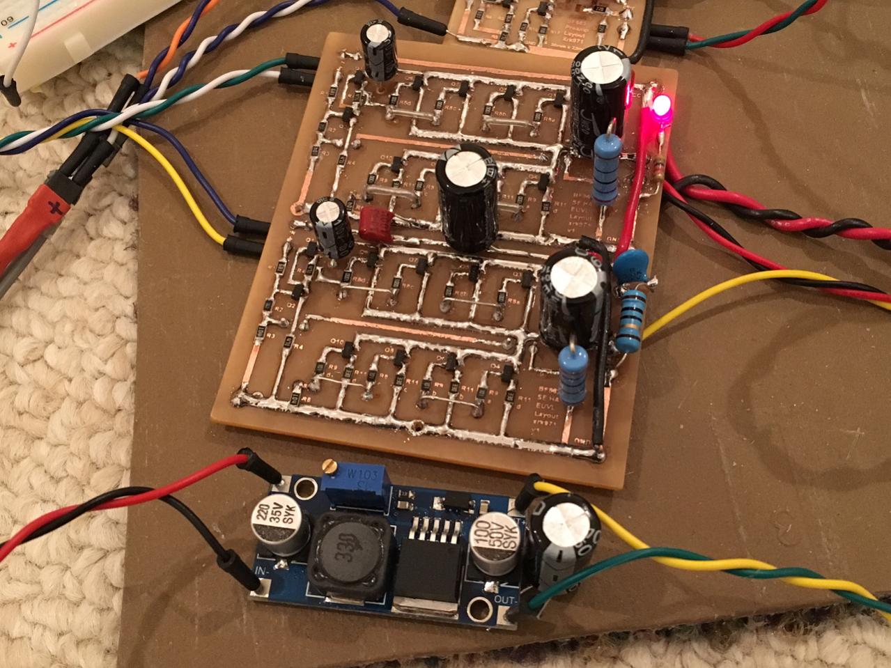
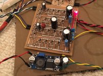
Amp works now! Listening to a few test tracks in one ear. So far so good. Very good dynamics and no noise or hiss using a XL6009 boost DC-DC converter. Will try higher voltages to see if it sounds better.
Amp works now! Listening to a few test tracks in one ear. So far so good. Very good dynamics and no noise or hiss using a XL6009 boost DC-DC converter. Will try higher voltages to see if it sounds better.
I have a stupid question - in the schematic, Rl represents the 32ohm headphone, not a load resistor in parallel with output to headphone right? I mistakenly put a 33R resistor on PCB and of course that sucks all the power from any headphone that is also plugged in. It wasn't until I put a DVM in volts AC on output that I see it playing music. But no sound from headphones. So delete RL right?
I had to change source resistors to 47R before I could get 10 to 12mA bias current in ea leg. Total bias is now 40 to 48mA. DC voltage upstream of blocking cap is rather high 10v rather than 7v (14v supply voltage now).
Looks like getting close to working though.
only 14V for your supply. That limits your maximum output into a high impedance load to ~4.5Vac
and to avoid higher distortion of the single ended stage your maximum output should be limited to about 50% of that i.e. ~2.2Vac
Replace the last resistor after the DC blocking cap with one >10k
This circuit has the capacitor connection that converts it to a push pull. It may give a higher output than a pure SE stage.
might be good if you think your absolute maximum peak voltages could exceed 2.2Vac. (3Vpk)Will try higher voltages to see if it sounds better.
Your post in the other Thread says 17V for supply. Did you hear any difference between 14 & 17?
BTW,
47r for a source resistor in these high gm BF862 seems very high. That's taking off >500mV from the Vgs !
and if your supply is only 14 to 17V then you don't have 12V across each jFET, only 6 to 8.5V and thus much less dissipation. You could go a bit higher in bias if you are happy with unclipped music @ 17Vdc supply.
Last edited:
I have a variable step up DC to DC booster so can run anything from 12v to 35v (the FETs are only rated for 25v I think so not good to exceed 24v probably. The output before the locking cap is not at the halfpoint of he voltage rail. It sits a few volts higher sonInwonder how to adjust this circuit to remove that asymmetry. It sounds quite good at 17v.
Like this.
I saw hat earlier but don't know what you are doing different other than dual rail with asymmetric supplies. That's a huge complication for a portable. Is there a ways to do with single rail supply? Can we force a virtual midpoint ground like how the B1 (rev1) does it?
- Home
- Amplifiers
- Pass Labs
- BF862 Preamp