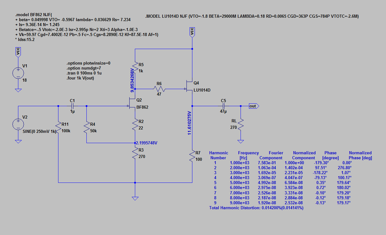
Take down R4 to 50k or so.
The problem is the gate leakage current of Q2. Over a high R4 it drives the gate voltage towards the rails and the circuit clips.
BF862 has high leakage compared to other JFETs. I have no clue, however, how accurate the spice model is regarding the gate current. I suspect it gets it too high, though.
So in a real circuit you can probably use higher R4 than in this modelling.
Take down R4 to 50k or so.
The problem is the gate leakage current of Q2. Over a high R4 it drives the gate voltage towards the rails and the circuit clips.
BF862 has high leakage compared to other JFETs. I have no clue, however, how accurate the spice model is regarding the gate current. I suspect it gets it too high, though.
So in a real circuit you can probably use higher R4 than in this modelling.
Thank you,
That worked like a charm and H2 is now very low. Should I do this in real life then?
Attachments
depends.
on your desired output swing and on your Q2 Idss.
you can measure the voltage at the drain of Q2. add the desired swing and make sure the peak stays off the rail.
on your desired output swing and on your Q2 Idss.
you can measure the voltage at the drain of Q2. add the desired swing and make sure the peak stays off the rail.
A Headamp with Juma's BF862 Pre as Input Stage
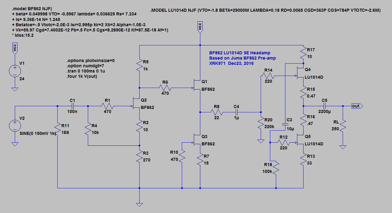
I am just playing around with LTSpice and took Juma's preamp and added a pair of LU1014D power JFETs for a SE class A output headamp. Probably lots of mistakes here and I welcome feedback and constructive criticism. I am not sure if this is a good LU1014D model (got it from here). I tried a more complex model from flg, found here but it kept giving me errors. If anyone can point me to the latest working model that would be great.
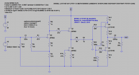
The schematic looks like this:
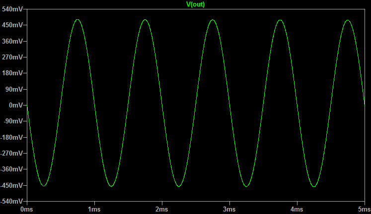
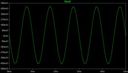
The scope of the output looks like this:
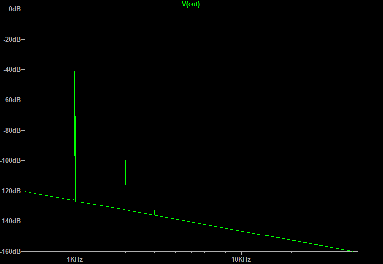
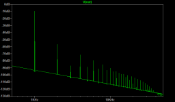
FFT looks like this:

It would probably play music but pretty high HD, although predominantly 2nd order so may actually sound lind of sweet if you like that sort of stuff. I have it driving a 250ohm headphone (my DT880's).
I am just playing around with LTSpice and took Juma's preamp and added a pair of LU1014D power JFETs for a SE class A output headamp. Probably lots of mistakes here and I welcome feedback and constructive criticism. I am not sure if this is a good LU1014D model (got it from here). I tried a more complex model from flg, found here but it kept giving me errors. If anyone can point me to the latest working model that would be great.
The schematic looks like this:
The scope of the output looks like this:
FFT looks like this:
It would probably play music but pretty high HD, although predominantly 2nd order so may actually sound lind of sweet if you like that sort of stuff. I have it driving a 250ohm headphone (my DT880's).
Attachments
Last edited:
Don't take sims too seriously. They are too often inconsistent with real life circuits (but they show some guidelines). Sim is good only up to certain point in the design process and then you have to build, measure and listen. Or you can abandon the second part - life is good in beautiful world of delusion...
lol😀Or you can abandon the second part - life is good in beautiful world of delusion...
Don't take sims too seriously. They are too often inconsistent with real life circuits (but they show some guidelines). Sim is good only up to certain point in the design process and then you have to build, measure and listen. Or you can abandon the second part - life is good in beautiful world of delusion...
I agree. But I have to start somewhere before building. This is a simple enough circuit and would be just an extension of the layout I already have with addition of two more JFETs. My last amp, the CFH9 sim'd beautifully but it wasn't it until it was built that Thimios caught a bad grounding scheme and proposed a fix. It works well now but would not have been caught but for the real thing built and debugged.
If one had asked the right questions, then the simulation model would have given the right answers and pointed to the trace layout error.I agree. But I have to start somewhere before building. This is a simple enough circuit and would be just an extension of the layout I already have with addition of two more JFETs. My last amp, the CFH9 sim'd beautifully but it wasn't it until it was built that Thimios caught a bad grounding scheme and proposed a fix. It works well now but would not have been caught but for the real thing built and debugged.
No it wouldn't. Stop lecturing stuff you don't understand.
What can be represented by models used in SPICE engine when real life parts (production process dependent) have characteristics that differ 10, 20, 30 even 100% ?
Why do people select and match parts ?
What can be represented by models used in SPICE engine when real life parts (production process dependent) have characteristics that differ 10, 20, 30 even 100% ?
Why do people select and match parts ?
Last edited:
Did you read the Thread discussing the performance problem?
It turned out that the major error was a connection to the wrong end of a resistor on both supply rails.
I'm not trying to lecture. I'm pointing out that simulations of models can reveal much.
It turned out that the major error was a connection to the wrong end of a resistor on both supply rails.
I'm not trying to lecture. I'm pointing out that simulations of models can reveal much.
There is no performance problem. Some are just lacking an understanding of how circuit works and what are design goals (I limit this to circuits I published in this thread).
You have not confirmed that you have read the Thread that Xrk referred to in his postThere is no performance problem. Some are just lacking an understanding of how circuit works and what are design goals (I limit this to circuits I published in this thread).
.the CFH9 sim'd beautifully but it wasn't it until it was built that Thimios caught a bad grounding scheme
To be clear, this is thread on CFH9 where problem was found by building.
http://www.diyaudio.com/forums/solid-state/294834-cfh7-amp-82.html#post4920073
But getting back to the BF862 and LU1014D amp I proposed, are there any glaring performance issues there?
http://www.diyaudio.com/forums/solid-state/294834-cfh7-amp-82.html#post4920073
But getting back to the BF862 and LU1014D amp I proposed, are there any glaring performance issues there?
I don't have that much time to read the whole story, but it's old and known concept. Understanding how the circuit works is essential.To be clear, this is thread on CFH9 where problem was found by building.
http://www.diyaudio.com/forums/solid-state/294834-cfh7-amp-82.html#post4920073
I wouldn't do it like that. Sorry, but I' don't have enough time to explain it in such a manner that you understand what's wrong with it.But getting back to the BF862 and LU1014D amp I proposed, are there any glaring performance issues there?
@xrk971 -- your life will be made easier if you use solder paste and a toaster oven!
the solder paste will hold the SMT devices to the pcb without squiggling.
there are a number of recipes for converting a toaster oven to a reasonably good reflow machine.
the solder paste will hold the SMT devices to the pcb without squiggling.
there are a number of recipes for converting a toaster oven to a reasonably good reflow machine.
@xrk971 -- your life will be made easier if you use solder paste and a toaster oven!
the solder paste will hold the SMT devices to the pcb without squiggling.
there are a number of recipes for converting a toaster oven to a reasonably good reflow machine.
Ha ha - I know. If I do too much more with sMT that's the way to go. They are kind of fun in a challenging way like a jigsaw puzzle to solder if not too many to do.
I like hand placing and soldering sm, it is so easy, if you get the technique down pat.
you have to use thin solder, 15 mil glow core works for me and of course a nice iron tip, tweezers,mag etc, simple tools.
stick with 0805/1206 if you are having difficulties with 0603
sure if you are going to do some volume, then a stencil/paste etc is the way to go, but I have never needed such in all my DIY stuff, even with DFN which is a PITA.
Hi rsavas,
Agree completely. Have you tried using liquid solder flux for smt work? It makes DFN packages bearable to do. I also use a 3mm screwdriver tip for ICs and a 2.4 mm tip for the smaller parts like resistors and capacitors and the like. Yes, you should clean up the flux afterwards, but the joints can look factory then.
-Chris
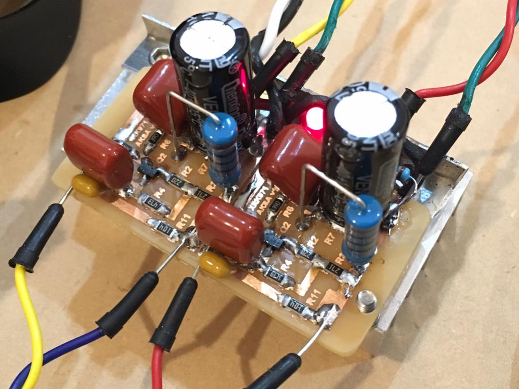
This preamp was developed into a class A head amp with Aksa's help and uses a simple 2 JFET source follower topology for some remarkable performance and sound quality. Simpler is sometimes better.
http://www.diyaudio.com/forums/solid-state/301164-mosfet-source-follower-headamp-15.html
Implemented:
http://www.diyaudio.com/forums/solid-state/301164-mosfet-source-follower-headamp-15.html
Implemented:
Last edited:
- Home
- Amplifiers
- Pass Labs
- BF862 Preamp