The B1 rev1 is cap coupled and doesn't need a midpoint.
I'm sure you mean the rev 2, and yes that is how you can do it.
Just make sure to use the same size cap on either side")
You have to play with source resistors for both top and bottom buffer jfets or strategically distribute the Idss of your devices to null the offset.
Or you keep the output cap just the same.
I'm sure you mean the rev 2, and yes that is how you can do it.
Just make sure to use the same size cap on either side
You have to play with source resistors for both top and bottom buffer jfets or strategically distribute the Idss of your devices to null the offset.
Or you keep the output cap just the same.
Member
Joined 2009
Paid Member
Many are reporting that glossy magazine paper is best.
I can't get any paper type to work well from my Brother laser printer.
I bought the recommended inkjet photo paper and it was pretty poor.
I have a small desktop Brother laser printer and it is hopeless - can't be used. The big commercial printer at work is fine, and as you say, glossy magazine paper is the best by far. I don't make my own boards anymore, too much trouble when China is so cheap.
The B1 rev1 is cap coupled and doesn't need a midpoint.
I'm sure you mean the rev 2, and yes that is how you can do it.
Just make sure to use the same size cap on either side
You have to play with source resistors for both top and bottom buffer jfets or strategically distribute the Idss of your devices to null the offset.
Or you keep the output cap just the same.
Look at the connection from the midpoint of the two 10k resistors to the input with 1M. Isn't that a virtual zero?
An externally hosted image should be here but it was not working when we last tested it.
Not really.
The two jFETs are selected to have the same Idss.
If both are operated at Idss then Vgs is zero.
When Vgs is zero the input sets the upper Source to the same voltage as the input.
That then allows the two 10k to hit that same voltage.
Your SE version does not have selected Idss jFETs so you don't know where the Vgs are sitting.
But the average gives the net output offset from mid voltage.
If you adopt the D.Feucht version which uses a source resistor in the upper and lower, then you can make a small adjustment in one or other to zero out the offset.
The way you printed your PCB you omitted the upper source resistors.
What you could do is swap out the 33r until you eventually hit the near midpoint.
When you had 1r0 were you above midpoint or below?
Then you moved to 47r, was that above or below midpoint?
Now that you have 33r, I think you are confirming your output is above midpoint.
Last edited:
Isn't that a virtual zero?
Yup, you are right. That way the supply voltage is shared between top and bottom JFET (within matching of Idss).
Its just that Nelson didn't bother to reference the voltage to the input or output. Others have turned that into a DC coupled B1.
You can do something similar like B1 rev1 in this circuit if you use say a 100kOhm resistor from all top gate resistors to positive and one to negative supply voltage while separating the buffer stage (right 8 FETs) from the gain stage (left 2 FETs) with a cap just as I showed before.
It's not paper at all. It is vinyl self adhesive shelving liner. Stick it to bond paper as backing then laserprint of photocopy design onto the smooth vinyl surface by sending both through machine. This particular brand goes through printer/copier fine and doesn't melt. It releases almost 100% of the toner onto the copper when heated with hot iron.
https://www.dollartree.com/Con-Tact...dhesive-Shelf-Liners-18x54-/p306003/index.pro
I tried this - Thank You for the tip!

(HP Laserjet 4050P)
Works as well or better than any glossy paper I've tried. cheaper than using expensive paper as well. You can really pour the heat on with the iron, doesn't melt.
I recommend chucking the board in water to cool before peeling otherwise the toner doesn't stick to the board well..
Forgot to mention the quench in cold water. Then peel back
At sharp angle. It is cheap $1 for 6.75sq ft. You can make a lot of boards. I did not realize that other materials can't handle heat as well - this stuff is impervious to the iron.
Credit for this trick goes to Still4given - the master of the home etched PCB.
At sharp angle. It is cheap $1 for 6.75sq ft. You can make a lot of boards. I did not realize that other materials can't handle heat as well - this stuff is impervious to the iron.
Credit for this trick goes to Still4given - the master of the home etched PCB.
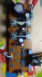
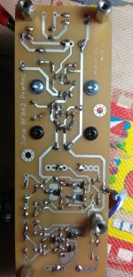
How did you achieve the "tinned" traces?My built Juma Pre Amp
Silver corrodes.
You will need to protect the silver coating from corrosion.
Silver also requires you to use a silver bearing solder, preferably the eutectic.
You will need to protect the silver coating from corrosion.
Silver also requires you to use a silver bearing solder, preferably the eutectic.
extracted from the solder wiki.Sn62Pb36Ag2 179[19] Pb yes Sn62.
Common in electronics. The strongest tin-lead solder. Appearance identical to Sn60Pb40 or Sn63Pb37. Crystals of Ag3Sn may be seen growing from the solder. Extended heat treatment leads to formation of crystals of binary alloys. Silver content decreases solubility of silver, making the alloy suitable for soldering silver-metallized surfaces, e.g. SMD capacitors and other silver-metallized ceramics.[7][28][32]
Not recommended for gold.[21]
General-purpose. 62%tin/Sn 36%lead/Pb 2%silver/Ag
Exposed silver gets dark tarnish (silver oxide?) but don't think that affects the electrical performance after parts soldered on. I have several older electrical PCB parts like DIP sockets with silver pins and they seem to work fine. Regular lead/tin rosin core solder seems to wet it pretty well.
ordinary 63/37 is not recommeded for soldering gold or silver over copper.Exposed silver gets dark tarnish (silver oxide?) but don't think that affects the electrical performance after parts soldered on. I have several older electrical PCB parts like DIP sockets with silver pins and they seem to work fine. Regular lead/tin rosin core solder seems to wet it pretty well.
Silver loaded is recommended for soldered to silvered component leads.
Hi Andrew,
While regular solder can leach some silver or gold out of the terminals, many are only plated in the areas where contact with the component leads will be. A one time installation using lead-tin solder isn't going to hurt the socket at all. Once the joint cools, chemistry action stops.
Have a look at the silver or gold plated sockets some time. You will see that the entire pin isn't fully plated. That would be a waste of precious metal. It stands to reason that the manufacturer would not allow this.
-Chris
You can achieve the same effect by using liquid flux, and some solder applied with loaded solder wick. That's how I've done my boards for years. You use lacquer thinner to remove the excess flux after "tinning" your PCB. This works much better than the tinning solution people normally would use, and it is a lot less expensive.
So, the tinning procedure is pretty simple. Use a large, wide chisel tip on your iron and get it up to 325~350 °C. Apply some solder in places to the traces you are going to tin. Heat the solder wick and allow it to soak up some solder. With the saturated end of the wick, apply heat and move that along the trace. You can keep a good pace and you'll quickly learn how much solder to use and how fast to go. I use wide solder wick as well. Using the normal skinny soldering tips won't work, nor will thin solder wick. The liquid flux you should always have on hand as in some situations it really saves the day (smt for one). Always remember to heat the solder wick and not the PCB trace. The heat will hit the trace just fine from the molten solder in the wick. If the end of the wick gets very ratty, trim it and continue.
I almost hate to ask, but how much does the silver plating compound cost? How about waste?
-Chris
I used to do the same thing anatech describes. Until one day it hit me: D'oh!! As long as I scrub the copper and clean it scrupulously, 5 minutes before soldering, the solder joints will be excellent. After that I don't care whether the top surface of the exposed copper (on traces and other regions that aren't soldered) does, or does not, oxidize. The interconnections are solidly made and reliable. What do I care whether the top surface gets a dark patina over time? It has no electrical impact.
So now I don't bother tinning. Scrub and solder immediately.
And in fact with Chinese PCBs so cheap and so quick (7 days from mouse click to finished boards in my hand in California), I don't bother making my own boards.
So now I don't bother tinning. Scrub and solder immediately.
And in fact with Chinese PCBs so cheap and so quick (7 days from mouse click to finished boards in my hand in California), I don't bother making my own boards.
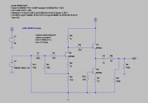
LTSpice model of Juma's BF862 Preamp
I am just learning LTSpice and tried modeling this preamp (using Elfishi's BF862 model):
LTSpice Schematic (I am driving 100k load so only need 1uF for C2):
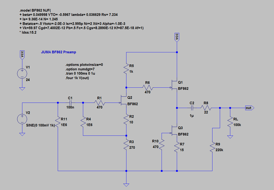
FFT:

I get really high distortion components. Did I do something wrong?
I am just learning LTSpice and tried modeling this preamp (using Elfishi's BF862 model):
LTSpice Schematic (I am driving 100k load so only need 1uF for C2):
FFT:
I get really high distortion components. Did I do something wrong?
Attachments

Last edited:
- Home
- Amplifiers
- Pass Labs
- BF862 Preamp