Yes, I wish I felt comfortable saying more now but the sentiment towards LTSPICE is very positive and our own internal SPICE is completely developed by us and does support the level 3 JFET model. Can the two meet I don't know.accident of acquisition?
Id is simply the current flowing through the drain pin.Thx,
I can see that conditional on Vds Idss is a fixed value.
I have the hunch, though, that you, too, mean Id(Vgs=0) when you write Idss. Could that be?
Idss is the current specified by the manufacturer when Vgs= zero AND Vds+Tj are as required by the specification. Idss is a special case that is defined.
Idss is generally used by all manufacturers and Forum Members to mean the same thing.
We Members are generally not able to measure Idss and that's mostly because we can't hold Tj to the specified temperature. But we can get close enough with a little care in all except the high Idss devices (i.e. Idss>20mA makes the junction heat too quickly and to too high a temperature).
Here's an Idss measurement technique that I've used on my kitchen table to measure JFET Idss. It keeps the JFET at room temperature by reducing its power dissipation to < 2 milliwatts. The secret? Low duty cycle pulse measurements.
Duty cycle is (53 usec / 318 msec) = 0.017%.
Even though the JFET's drain current is 1.1 amperes (!) and its drain-to-source voltage is 5.72 volts, its power dissipation is only (0.017 / 100) * 5.72 * 1.1 = 1.07 milliwatts.
Multiplying power dissipation times thermal resistance (357 degrees C / watt) we find that the JFET's internal junction temperature is 0.38 degrees C higher than the room temperature air.
Have you compared the 861 datasheet to the 862 datasheet.good idea,but why not use BF861C ? the yfs is best
I read them as 862 Yfs is higher than 861.
Build report
Done.
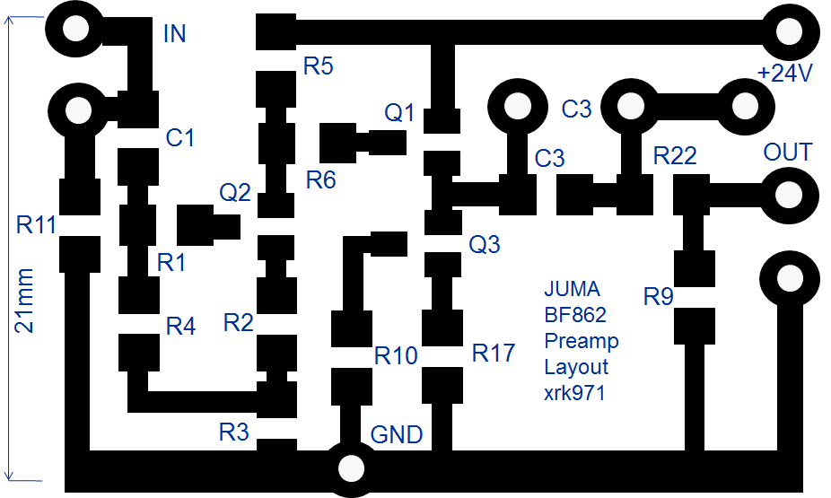
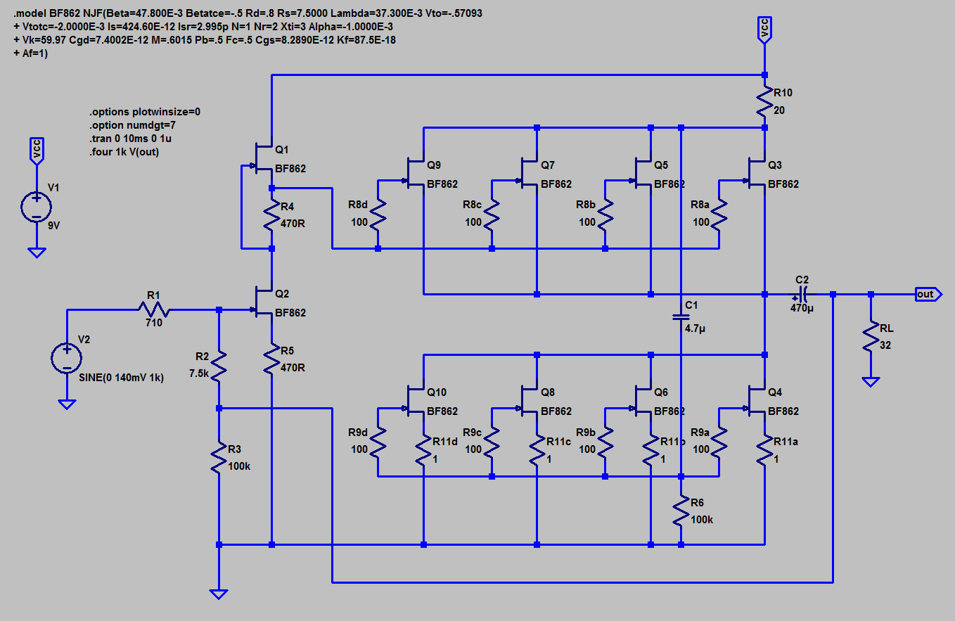
I built the BF862-pre according to the schematic shown here. It feeds my M2 from a DACmagic.
The power is supplied from the positive rail of the M2 with a voltage of 21.7V. It is next run through 10Ohms and over 4700uF to feed a cap multiplier as found here. Resulting voltage at the top of R5 is 21.0V. Only a cap multiplier is not sufficient to remove the ripple from the rail, when adding the RC its gone.
I adjusted R5, R6, and R4 to 887, 360 and 15 Ohm, respectively. With these values I can drive the pre to turn out 3.9V peak (7.8 peak-to-peak) before a triangle waveform starts to round off.
Done.
I built the BF862-pre according to the schematic shown here. It feeds my M2 from a DACmagic.
The power is supplied from the positive rail of the M2 with a voltage of 21.7V. It is next run through 10Ohms and over 4700uF to feed a cap multiplier as found here. Resulting voltage at the top of R5 is 21.0V. Only a cap multiplier is not sufficient to remove the ripple from the rail, when adding the RC its gone.
I adjusted R5, R6, and R4 to 887, 360 and 15 Ohm, respectively. With these values I can drive the pre to turn out 3.9V peak (7.8 peak-to-peak) before a triangle waveform starts to round off.
sismik,
there is an easier way to make this pre (see attached schematic).
That way we don't need the negative PS anymore and the gain is easily adjusted by changing only the value of R3 (in reasonable range: from 100R for 17dB gain to 470R for 6dB gain).
Of course, this demands the use of an input cap (C1) but since it's of small value (47-100 nF) it's easy to fit the good one (WIMA MKP10 or whatever one likes).
Thank you Juma for a great preamp design. Works wonderfully well - transparent and very quiet. Just the right amount of gain and single rail supply. Very cost effective for such a superb design and performance.
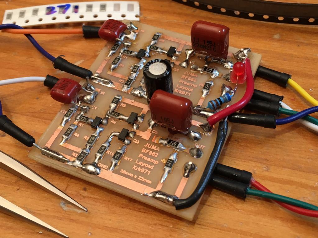
I am using 47R for R2 based on trial and error to get Ids down to sub 10mA. Also just usin 100nF 100v MKT on input and 1uF 230v MKT on output (load is 100k so fine there).
I have a question for Juma: can Q1 and Q3 be paralleled (say 5 pairs) with source resistors to make a nifty little compact class A headamp?
Last edited:
Just came across this thread. Are there boards available for the single supply version? Like the ones in the Pic? Thanks
I etched them myself - I can post a PNG file for the iron on transfer if you want. No Gerbers available as the layout was hand drawn in PowerPoint 🙂
Last edited:
can Q1 and Q3 be paralleled (say 5 pairs) with source resistors to make a nifty little compact class A headamp?
You can "turbo" the buffer stage like e.g. shown here. Less than 30 Ohm Zout with every FET pair.
Or you can capitalise on another sugestion of Juma's shown here and use the buffer stage BF862 in a CFP configuration. This gets you on the order of 2 Ohm Zout.
Depending on the Idss of your FET, the input swing and the supply voltage you may want to do some loadlining of the gain stage. I only had 21V or so available and had to change resistors to avoid clipping.
Hi X,please post the PNG😉I etched them myself - I can post a PNG file for the iron on transfer if you want. No Gerbers available as the layout was hand drawn in PowerPoint 🙂
BF862 Preamp Layout v2
Here it is, with some improvements added based on lessons learned with version 1. I added through holes for input film cap, and more holes for connection wires. The external border enclosing the traces (for one channel) should be scaled to 35mm x 23mm. You can check with a ruler and adjust scale on your printer until it works.
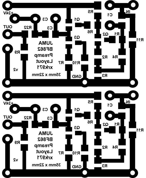
Here it is, with some improvements added based on lessons learned with version 1. I added through holes for input film cap, and more holes for connection wires. The external border enclosing the traces (for one channel) should be scaled to 35mm x 23mm. You can check with a ruler and adjust scale on your printer until it works.
Attachments
You can "turbo" the buffer stage like e.g. shown here. Less than 30 Ohm Zout with every FET pair.
Or you can capitalise on another sugestion of Juma's shown here and use the buffer stage BF862 in a CFP configuration. This gets you on the order of 2 Ohm Zout.
Depending on the Idss of your FET, the input swing and the supply voltage you may want to do some loadlining of the gain stage. I only had 21V or so available and had to change resistors to avoid clipping.
Thanks for the links. I was also thinking something along the lines of this one by EUVL:
http://www.diyaudio.com/forums/solid-state/298026-tin-fets-headphone-amplifier-2.html
I have never made boards before. I'm sure this is the right place to discover though. I was looking at the Pre-sensitized boards from Parts Express. Would that work? What is the process?
Transparent sheets and UV light...maybe use the sun?
However, I think the trace has to be unblocked and the rest of the board has to be blocked.
The posted traces above is for etching away the non-trace portion. Chemical bath.
However, I think the trace has to be unblocked and the rest of the board has to be blocked.
The posted traces above is for etching away the non-trace portion. Chemical bath.
Last edited:
I played a bit on eagle. I will try the preamp at some point. I already have the jfets.
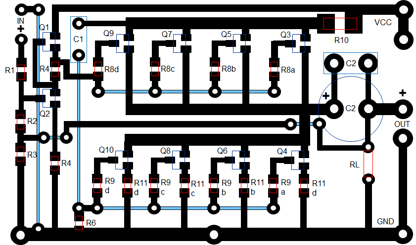
Here is my layout
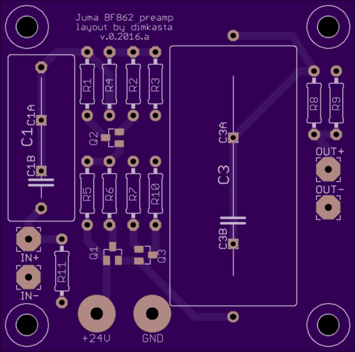
Untested so far, but I am attaching the eagle files, so feel free to check them and make any changes you want
About boards, the cost from china is so low these days that it just does not worth the effort or the danger to etch them yourself (unless you enjoy the process)
Here is my layout
Untested so far, but I am attaching the eagle files, so feel free to check them and make any changes you want
About boards, the cost from china is so low these days that it just does not worth the effort or the danger to etch them yourself (unless you enjoy the process)
Attachments
Thanks for the links. I was also thinking something along the lines of this one by EUVL:
http://www.diyaudio.com/forums/solid-state/298026-tin-fets-headphone-amplifier-2.html
Maybe something like this? 39mm x 64mm:
Attachments

I have never made boards before. I'm sure this is the right place to discover though. I was looking at the Pre-sensitized boards from Parts Express. Would that work? What is the process?
I might start another "Easy Peasy" etching your own PCB's with household materials.
Use laser printer to make transfers onto special paper. Iron on transfer to copper. Etch with muriatic acid and peroxide (or vinegar but slower).
- Home
- Amplifiers
- Pass Labs
- BF862 Preamp