Thanks, Hugh. I have a neat little DC to DC step up converter planned for the power supply system so 12v (or even LiPo 3.7v) is a possibility. The baseline plan is to use for desktop amp so 12v SMPS PSU that comes with typical external DVD ROM/HDD/router will work just fine and plentiful and cheap.
So I am debating whether or not to start with a fresh PCB or modify a existing one. One question is how can I bend the legs of the IRF to allow it to actually bolt to the bottom of the case for a heatsink. The orientation would allow this with a simple L bracket heat spreader. This way, the existing pot goes straight to the front panel along with the input and output jack. This will be super compact allowing for a nice low ESR cap bank.
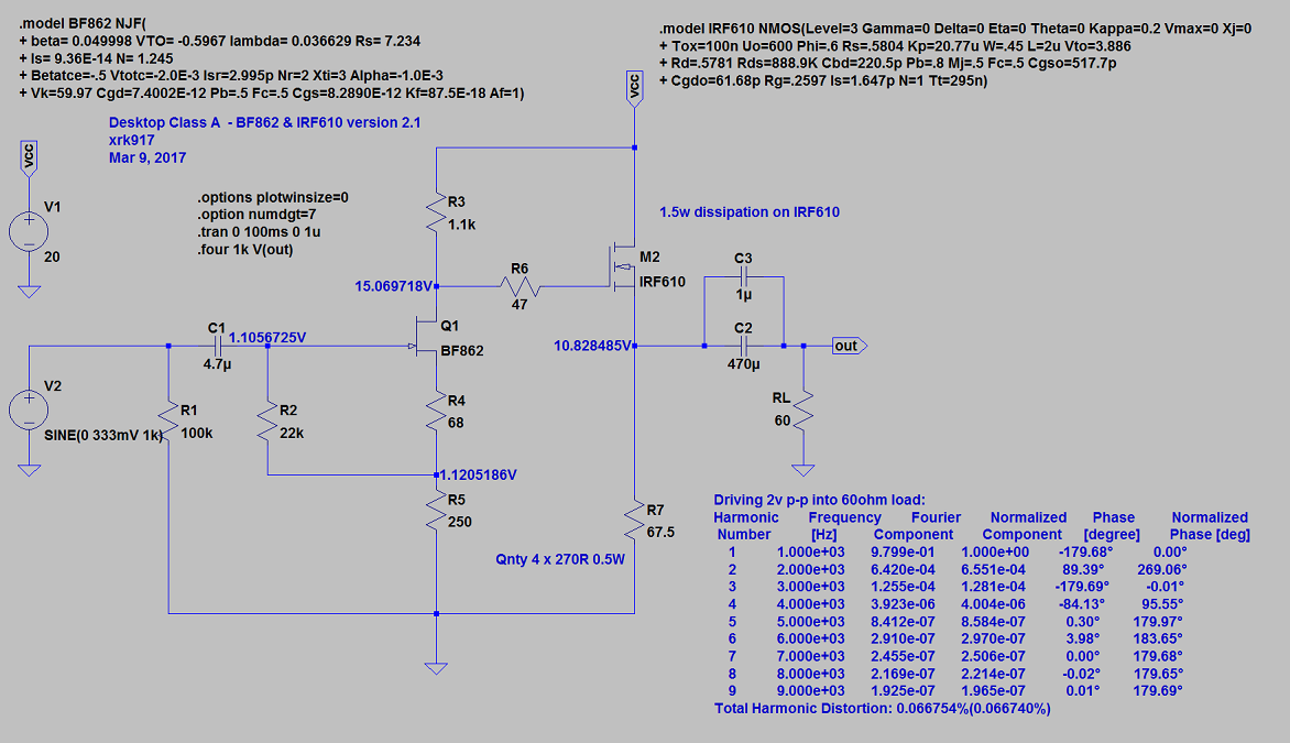
Desktop Class A BF862 and IRF610 Source Follower
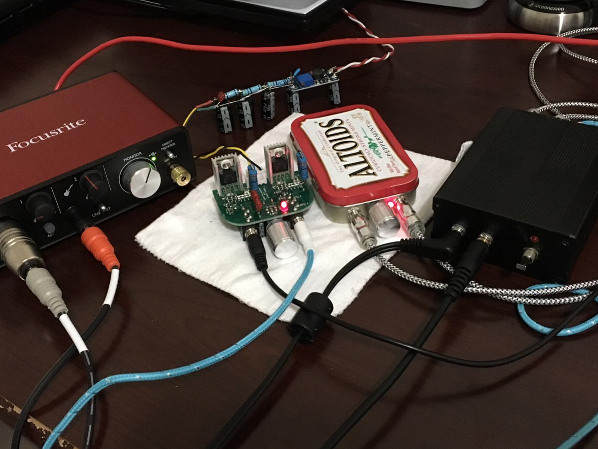
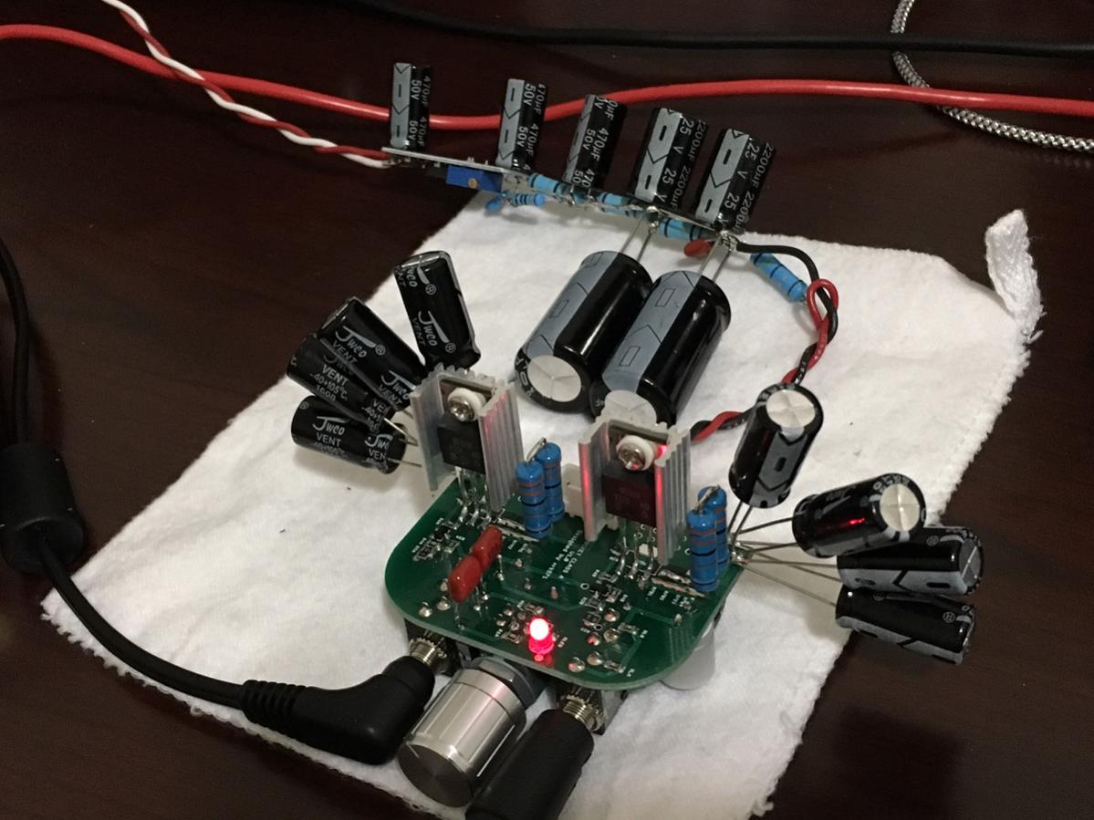
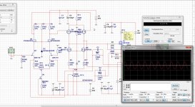
I was able to implement the above circuit using one of the pocket class A amp boards as the basis. I am using two 33R 2W resistors in series for the main power resistor. Two 2k2 in parallel give me 1.1k for the JFET Drain, 1000uF 16V OSCONS on the outputs bypassed with 1uF Wima's. On input using 10uF 63c electrolytic bypassed with 0.1uF 100v film cap. 20v supply provided by 19v SMPS going into step up DC-DC converter for 20.0v. Voltage at source of IRF610 is 9.38v and 9.43v which is about 140mA bias over the 66R resistors.


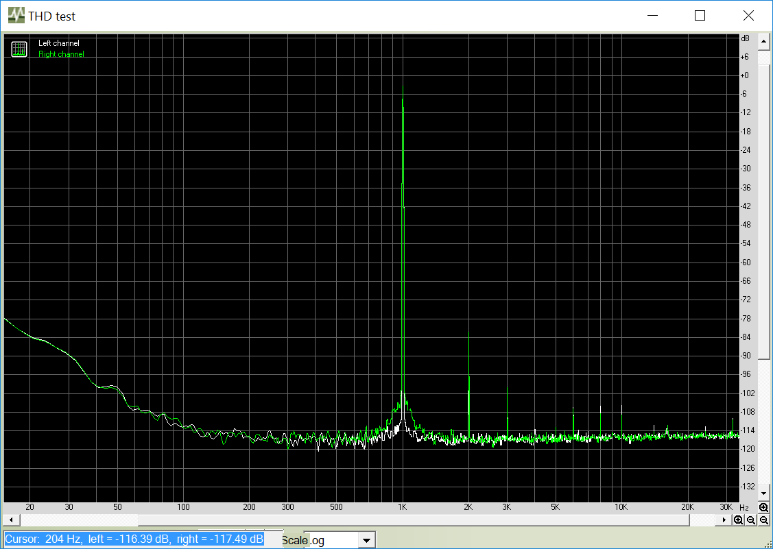
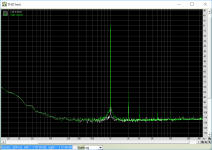
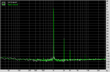
I listened to it first before measuring and it was powerful but sounded kind of dry. I do not hear any hiss or hum. The measurement shows a broadband white noise at covers DC to audio. The FFT shows that the H2 is indedd very low, hence dry sounding. The SMPS has broadband white noise i the LF's sneaking through the 470uF//4.7R//470uF//4.7R//2200uF//4.7//200uF CRCRCRC filter. Looks like I may need some bigger caps in my CRC to get the broad band noise down.
Anyhow the circuit works - and will need some more work to optimize the noise problem, also probably change R4 to get harmonic profile desired.
THD came in at 0.0078% (too low for my taste), dynamic range is 85dB due to the broad noise hump from the SMPS, stereo crosstalk is -69.2dB.
I am listening to some test tracks now, sounds very nice - great dynamics and headroom. Can get very loud on transients. Daft Punk has some slamming bass. I do not hear any hiss or noise. The measurement does show a low level (-84dB) broadband noise floor rising up below 100Hz. I think this has a lot of promise with some tweaks on a few resistor values and a cleaner PSU.
I was able to implement the above circuit using one of the pocket class A amp boards as the basis. I am using two 33R 2W resistors in series for the main power resistor. Two 2k2 in parallel give me 1.1k for the JFET Drain, 1000uF 16V OSCONS on the outputs bypassed with 1uF Wima's. On input using 10uF 63c electrolytic bypassed with 0.1uF 100v film cap. 20v supply provided by 19v SMPS going into step up DC-DC converter for 20.0v. Voltage at source of IRF610 is 9.38v and 9.43v which is about 140mA bias over the 66R resistors.
I listened to it first before measuring and it was powerful but sounded kind of dry. I do not hear any hiss or hum. The measurement shows a broadband white noise at covers DC to audio. The FFT shows that the H2 is indedd very low, hence dry sounding. The SMPS has broadband white noise i the LF's sneaking through the 470uF//4.7R//470uF//4.7R//2200uF//4.7//200uF CRCRCRC filter. Looks like I may need some bigger caps in my CRC to get the broad band noise down.
Anyhow the circuit works - and will need some more work to optimize the noise problem, also probably change R4 to get harmonic profile desired.
THD came in at 0.0078% (too low for my taste), dynamic range is 85dB due to the broad noise hump from the SMPS, stereo crosstalk is -69.2dB.
I am listening to some test tracks now, sounds very nice - great dynamics and headroom. Can get very loud on transients. Daft Punk has some slamming bass. I do not hear any hiss or noise. The measurement does show a low level (-84dB) broadband noise floor rising up below 100Hz. I think this has a lot of promise with some tweaks on a few resistor values and a cleaner PSU.
Attachments
Last edited:
(emphasis added)...THD came in at 0.0078% (too low for my taste)...
And, yet, you favored the 2SA1837 CFP amp over many others despite the fact that it offers even lower distortion... Do we want hi-fi equipment or effects boxes? Seems you've chosen the latter, despite your previous claims that you are overly sensitive to distortion.
🙄
Through that? I very much doubt it. More like around it. Since you did not hear anything in headphones, the problem may be common-mode noise from the SMPS on the ground making its way to PE via your measurement PC.I listened to it first before measuring and it was powerful but sounded kind of dry. I do not hear any hiss or hum. The measurement shows a broadband white noise at covers DC to audio. The FFT shows that the H2 is indedd very low, hence dry sounding. The SMPS has broadband white noise i the LF's sneaking through the 470uF//4.7R//470uF//4.7R//2200uF//4.7//200uF CRCRCRC filter.
*sigh*THD came in at 0.0078% (too low for my taste),
What's IMD(f) like?
BTW, you should be getting better stereo crosstalk than just 70 dB unloaded. Smells like too much shared ground return between the channels.
Last edited:
This is first sound test. Let me add a proper cap bank to boost the capacity of the rail caps. Same 2200uF x 2 as used on 50mA bias version and now bias is 3x higher. Probably need to boost caps to 6800uF x 2 to have similar stereo crosstalk separation. I knew you guys would have fun with my distortion comment. For the record, sensitive to odd order distortion 🙂. Let's see if a 9 x 2200uF cap bank will improve things.
I am amused by the outrage at distortion levels........
Only the technical ignore the subjective, seeking only the zero distortion ideal.
Guys, there is no perfection, and most people don't like zero distortion.
HD
Only the technical ignore the subjective, seeking only the zero distortion ideal.
Guys, there is no perfection, and most people don't like zero distortion.
HD
True - the lowest distortion amps were not picked by listeners in my blind test. Music is entertainment isn't it? It should sound good not dry and sterile.
I guess there are those who listen to music vs those who want to analyze their music.
I guess there are those who listen to music vs those who want to analyze their music.
I believe it's just an ideology issue.
People love to love an ideal, generally in technical issues, politics, religion, love itself; the reality is usually unloved.
HD
People love to love an ideal, generally in technical issues, politics, religion, love itself; the reality is usually unloved.
HD
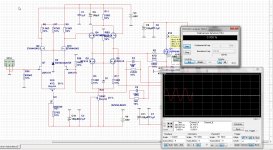
I dropped the supply rail down to 16.5v (trim pot on DC step up), also now using 12v SMPS from external Maxtor HD. The harmonic profile looks much better now. I am running 93mA bias in IRF610 and 5.5mA in the BF862. I used my AB switch box and compared with the Pocket Class A and really could not tell a difference in sound with my 250ohm headphones at 140mA, so figured just drop down and reduce heat output by a lot.
AB Test Setup:
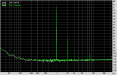
FFT at 16.5v supply rail:

Just need to work on getting better isolation from that broad rise below 100Hz.
AB Test Setup:
FFT at 16.5v supply rail:
Just need to work on getting better isolation from that broad rise below 100Hz.
Attachments

Last edited:
Through that? I very much doubt it. More like around it. Since you did not hear anything in headphones, the problem may be common-mode noise from the SMPS on the ground making its way to PE via your measurement PC.
*sigh*
What's IMD(f) like?
BTW, you should be getting better stereo crosstalk than just 70 dB unloaded. Smells like too much shared ground return between the channels.
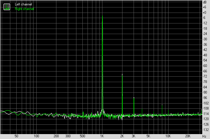
Well, lowering bias to 93mA and adding 10mF x 2 on the final CRC and then 8 x 2200uF cap bank on the amp itself seems to have fixed everything.
No more broad white noise below 100Hz, stereo crosstalk is now -76.2dB, THD is now 0.048%, IMD is 0.046%, harmonic profile looks really nice now.
Here is the "Iron Throne" Cap Bank and you can see the two big 10mF caps added to the final CRC:
Total power train looks like this:
12vdc 3A SMPS//470uF//DC-DC (19.65v)//470uF//4.7R//470uF//4.7R//12.2mF//4.7R//12.2mF//0.47R//17.6mF(cap bank)//Vcc rail (16.5v)
So I think I achieved my goal of a very clean low ripple (-114dB) power supply that is mains powered without any heroic efforts (no shunt regs or cap multiplier, etc). Just SMPS, DC-DC-step up, and passive CRC filtering.
Oh, and how does it sound now? Fantastic! Deep dark background, super dynamics, powerful bass that grabs you. Very engaging vivid presentation.
Attachments
Last edited:
Now that the circuit is proven to work I will work with BDHM to make a PCB for a desktop amp. I am thinking of using a Eurocard 3U (100mm x 160mm) format so that it can fit into a standard case like this one.
http://www.mouser.com/Search/m_Prod...98UY7qTWFfAemoWKbAPuz1BzE9-HXvbz4YaAs868P8HAQ
This version has a top that slides out for access:
https://www.amazon.com/gp/aw/d/B004RIEZV6/
Mouser carries it too I think.
There should be plenty of room for PCB mounted input jacks (3.5mm and RCA) output jacks (volume knobs and a nice capacitor bank for the PSU. Input power will be 5.5mm standard wall wart jack.
Something like this should work well:
https://www.amazon.com/gp/aw/d/B00Q2E5IXW/
We will be using an MT306 DC step up converter to go from 12v to 16.5v up to 20v (adjustable depending on how little distortion you want vs Class A heat).
http://www.mouser.com/Search/m_Prod...98UY7qTWFfAemoWKbAPuz1BzE9-HXvbz4YaAs868P8HAQ
This version has a top that slides out for access:
https://www.amazon.com/gp/aw/d/B004RIEZV6/
Mouser carries it too I think.
An externally hosted image should be here but it was not working when we last tested it.
There should be plenty of room for PCB mounted input jacks (3.5mm and RCA) output jacks (volume knobs and a nice capacitor bank for the PSU. Input power will be 5.5mm standard wall wart jack.
Something like this should work well:
https://www.amazon.com/gp/aw/d/B00Q2E5IXW/
We will be using an MT306 DC step up converter to go from 12v to 16.5v up to 20v (adjustable depending on how little distortion you want vs Class A heat).
Last edited:
Now that the circuit is proven to work I will work with BDHM to make a PCB for a desktop amp.
Bring it on! 🙂
I've used one of the 1455 boxes before, but different size. The Hammond datasheet for the part you mention has a slide-out bottom. Flip it over for a slide-out top:
http://www.hammondmfg.com/pdf/1455K1201.pdf
http://www.hammondmfg.com/pdf/1455K1201.pdf
Last edited:
Too good to be true
X,
Earlier in this thread you posted the "as built" schematic of the winner, the BF862-2SA1837 combo.
For fun, change R2=75R and R7=27R in your model, and then run it again. Notice any change?
When I made that change, the THD dropped an order of magnitude. Seems too good to be true.
I'd be interested to know what you see.
Mike
It's true - I knew this already and saw the same thing and the amp in reality and can be even lower. That Toshiba 2SA1837 is a special transistor.
If you recall, the measured THD on blind comparison was 0.0056% and depending on resistor tweaks, can be 0.002%.
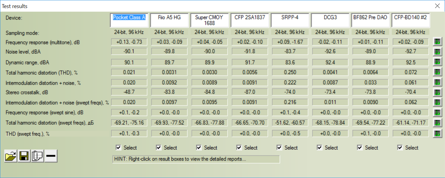
If you recall, the measured THD on blind comparison was 0.0056% and depending on resistor tweaks, can be 0.002%.
Last edited:
If you recall, the measured THD on blind comparison was 0.0056% and depending on resistor tweaks, can be 0.002%.
Then the 0.03% (in text) on the model was a typo?
No, the model predicts higher THD than measured. I guess the model of the 2SA1837 may not be accurate enough.
No, the model predicts higher THD than measured. I guess the model of the 2SA1837 may not be accurate enough.
OK, just curious. It is really hard to believe that a less then 10% change in resistor values could give an order of magnitude change. I'm still not sure I believe what the models are telling me.
Well, lowering bias to 93mA and adding 10mF x 2 on the final CRC and then 8 x 2200uF cap bank on the amp itself seems to have fixed everything.
No more broad white noise below 100Hz, stereo crosstalk is now -76.2dB, THD is now 0.048%, IMD is 0.046%, harmonic profile looks really nice now.
Here is the "Iron Throne" Cap Bank and you can see the two big 10mF caps added to the final CRC:
Total power train looks like this:
12vdc 3A SMPS//470uF//DC-DC (19.65v)//470uF//4.7R//470uF//4.7R//12.2mF//4.7R//12.2mF//0.47R//17.6mF(cap bank)//Vcc rail (16.5v)
So I think I achieved my goal of a very clean low ripple (-114dB) power supply that is mains powered without any heroic efforts (no shunt regs or cap multiplier, etc). Just SMPS, DC-DC-step up, and passive CRC filtering.
Oh, and how does it sound now? Fantastic! Deep dark background, super dynamics, powerful bass that grabs you. Very engaging vivid presentation.
Looks good X, I see you are a headphone fan, I am started again some type of amps, but need to take attention to one, I do sometimes to much in one go, not good.
But has in the D section a nice low distortion one with discrete comparator, I need some HF transistors for it with low pn capaciance.
The Circlotron X do not work good, the current feedback one who has a long tail pair do not work fine and has a pretty high HD this is because of unbalance in the long tail, when I use voltage feedback from one circlotron half it do go to 0.006. See pictures of first current feedback and second has voltage feedback, but need a opamp for make diff output to single for feedback so it can even be lower, however I do not like feedback special the voltage one so we go to a balanced version of this amp, with a unbalance to balance opamp as input or a transformer.
Back on topic again, nice tests you do, no wonder X is so quiet.
regards
Attachments
- Home
- Amplifiers
- Headphone Systems
- BF862 based SE Class A Headamp without the HEAT