😀Very nice work BDHM!
Thanks!


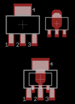
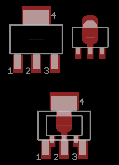
I've just slapped one on the board, and SOT89 is quite a bit smaller. One could indeed place the SOT89 on the original pad, but contact area would be minimal.Just checked data sheet, pads are indeed GDS, with D on 4th so should be compatible if spacing is correct.
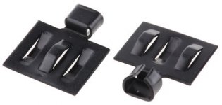
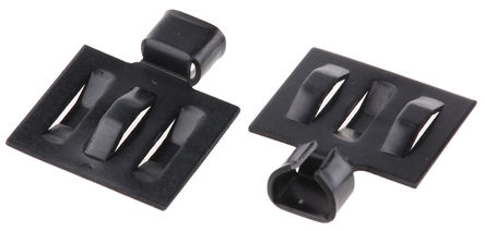
Plus there would only be ~0.3mm clearance between the outer pins and the pad for the middle pin. See attached image, the two side by side and then stacked on top.
I also wonder what the reduced size would mean for thermal dissipation.
I can totally play around with the footprint though, and see if a good compromise can be made
Attachments
Wow, that's tiny! I am not sure if having a change in THD from 0.014% to 0.011% is justified by the reduced thermal contact footprint. I could try swapping it out
on my current prototype to see if it works. Thanks for showing the size comparison.
on my current prototype to see if it works. Thanks for showing the size comparison.

Nice! You got it to fit as through hole except for JFETs! Is that a TO220 ZVN4306? It will have to rely on air convection or tiny TO92 heatsinks?
This version may be indeed a lot more palatable for SMT scaredycats 🙂
This version may be indeed a lot more palatable for SMT scaredycats 🙂
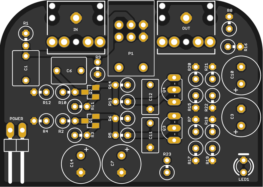
had a thought today that if we make the PCB in a hybrid SMT and through hole for all non-actives, people might not be as intimidated to make this amp without worrying about soldering all those little resistors. It is simple enough that we may just have enough room. What do you all think?
+1 for through-hole soldering preference! Ill attempt it either way, but this makes it less daunting.
Hi BDHM,
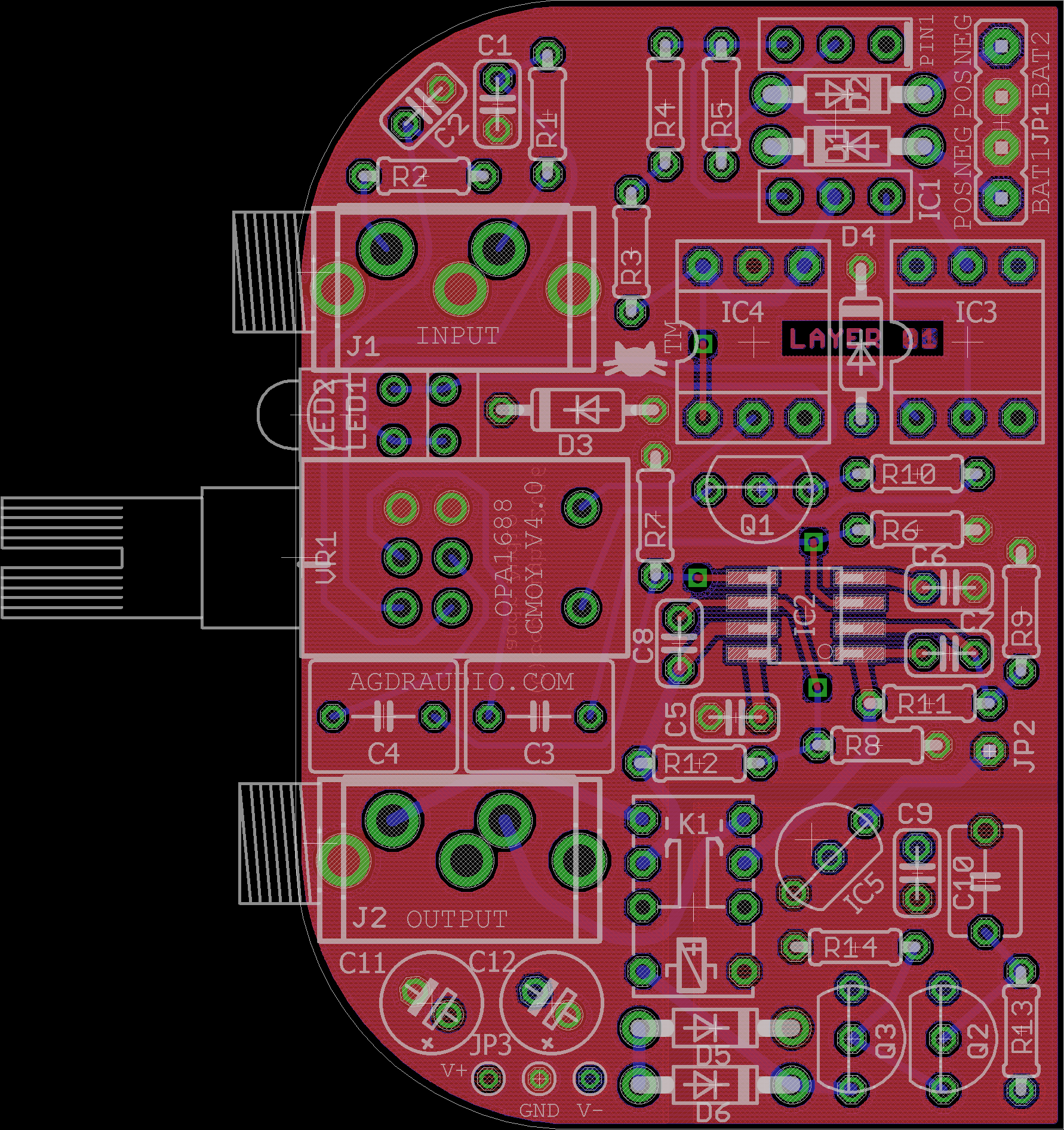
I am concerned that the 3.5mm jacks you have don't have enough spacing (center to center) with the volume knob shaft to allow a regular volume knob to fit without interference. Please look at the jacks used on Agdr's. Super CMOY - they are narrow profileand allow you actually squeeze a pair of input caps and an LED in between and permit sufficient clearance for a knob.
This may free up some space on main area by moving caps and LeD away. Also LED on end next to pot shaft is preferable.
Thanks for the great work!
Yup! The BF862 is only available in SMT. I could easily place provision for 2SK170s for those who can get em.Nice! You got it to fit as through hole except for JFETs!
Indeedy: http://www.mouser.co.za/ProductDeta...=sGAEpiMZZMshyDBzk1/Wi0w8OutPcgKpEXQ7Oa3Ayf4=Is that a TO220 ZVN4306? It will have to rely on air convection or tiny TO92 heatsinks?
This is why I asked for consensus on 3.5mm jack 😀. Does anyone know what make and model the ones Agdr used are? Otherwise, these are decent and also quite slim: Product – LumbergPlease look at the jacks used on Agdr's. Super CMOY
Attachments
The part no is in the BOM in Agdr's thread post 1. It's from Mouser I think. How is the photo of the thing you posted supposed to be used as a 3.5mm jack?
Oh I see that's the TO92 heatsink.
The linked part is indeed compact but has no threaded nut for securing to the panel and must rely on the PCB for stress relief of insertion and removal. That may break the boards prematurely as they are only anchored via volume pot.

Oh I see that's the TO92 heatsink.
The linked part is indeed compact but has no threaded nut for securing to the panel and must rely on the PCB for stress relief of insertion and removal. That may break the boards prematurely as they are only anchored via volume pot.
Last edited:
I could easily place provision for 2SK170s for those who can get em.
A replacement part, the Linear Systems LSK170, is widely available. For instance, from here.
Last edited:
Although to use 2SK170's I would need to re-optimize the resistor values in simulation and in practice to get the correct bias value at the MOSFET and correct currents.
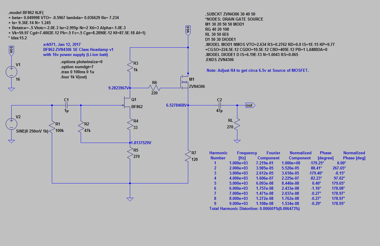
Revised sims with Li-ion batt
I just noticed that a rechargeable 9v Li-ion battery is not really 9v but 8.4v and under load is more like 8v. So I set power rail at 16v and put in as built parts (except for R2 which needs manual adjustment for particular Idss of JFET). The predicted THD is now a very respectable 0.0065% at full volume. The FFT is still very nice looking.
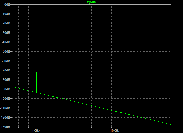
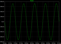
And FFT (with grid lines this time) at 1.40v peak-peak output level:
1k sine wave at 1.4v p-p:
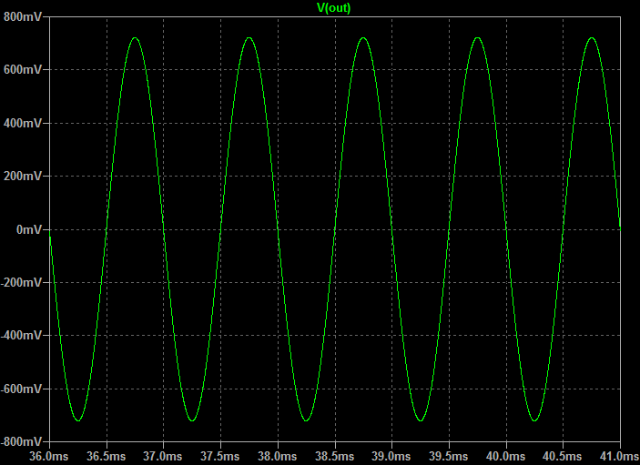
I just noticed that a rechargeable 9v Li-ion battery is not really 9v but 8.4v and under load is more like 8v. So I set power rail at 16v and put in as built parts (except for R2 which needs manual adjustment for particular Idss of JFET). The predicted THD is now a very respectable 0.0065% at full volume. The FFT is still very nice looking.
And FFT (with grid lines this time) at 1.40v peak-peak output level:
1k sine wave at 1.4v p-p:
Attachments
Last edited:
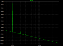
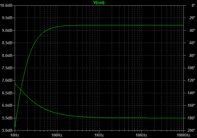
Frequency response and phase for above. -3dB point is about 12Hz - phase is off about 50deg at 12Hz but is within 20deg above 35Hz. Use of larger caps would flatten phase but at expense of non-euphonic (H3 same as H2) harmonic distortion profile. I would rather take 20deg shift down to 35Hz.
Attachments
C2 and the 270r load is setting the ~12Hz roll off. And starts to have an effect from ~120Hz downwards.
If you add any headphone load in parallel to the 270r, then the roll-off frequency will move a bit higher.
I suspect this high roll-off frequency is what you heard when you made comment on the mid range frequencies.
If you add any headphone load in parallel to the 270r, then the roll-off frequency will move a bit higher.
I suspect this high roll-off frequency is what you heard when you made comment on the mid range frequencies.
Let me check what happens with 60ohm headphones and 330uF cap. That's the biggest low ESR 25v oscon.
I don't think you need a special electrolytic to realise the low bass performance.
Yes, using ordinary electrolytics might introduce some audible effects, but I have never, so far, heard them.
A pair of back to back 1mF gives an effective 500uF and allows 60ohms to go down to ~10Hz for F-1dB
If you want another octave, then use 4 off 1mF in series parallel with two in back to back format and two in front to front format and parallel them for an effective 1mF and f-1dB @ ~5Hz.
If you sim this and get the capacitance high enough, the sim should start to show what other components might limit the pass band.
I suspect the 1uF is not limiting the input to any significant effect.
Last edited:
After 45 mins of trying to find an Eagle library for that part, my Google-Fu has failed me 😉. I've asked agdr to send it to me. If that doesn't work out I'll have to create the package - but I haven't done that before so it might take a while to do it properly.Please look at the jacks used on Agdr's.
*Brody voice* We're going to need a bigger board 😀If you want another octave, then use 4 off 1mF in series parallel with two in back to back format and two in front to front format and parallel them for an effective 1mF and f-1dB @ ~5Hz..
I don't think back-back 1000uF's are needed. A small 330uF 25v on a 60ohm load will get -2dB at 10Hz.
I've not noticed that relationship.You don't think having low ESR of 20mOhms might improve bass authority?
I just go big enough so that the output cap does not have any significant AC signal across it. I much prefer to passive filter at the input where a small plastic film cap can be used.
But going small electro on the output might suit the higher distortions you are aiming for.
An electro used as a filter will have more distortion of the signal that is being filtered, i.e. the bass frequencies. than an electro that is just DC blocking without any AC signal across it.
Not suitable for an altoid, too big, but is a good solution in the lead to the output socket rather than on board for a bigger enclosure...............
*Brody voice* We're going to need a bigger board .......
- Home
- Amplifiers
- Headphone Systems
- BF862 based SE Class A Headamp without the HEAT