Pocket Class A
New amp I just made last night - truly CMOY sized but SE Class A MOSFET output. BF862 input stage and ZVN4306 output with about 67mA bias current. Sounds very promising. 🙂
http://www.diyaudio.com/forums/solid-state/301164-mosfet-source-follower-headamp-24.html#post4944112
New amp I just made last night - truly CMOY sized but SE Class A MOSFET output. BF862 input stage and ZVN4306 output with about 67mA bias current. Sounds very promising. 🙂
http://www.diyaudio.com/forums/solid-state/301164-mosfet-source-follower-headamp-24.html#post4944112
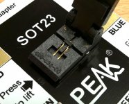
How do you test for idss those smd parts(bf862) without soldering them?
With a small board like this. I had to flow a tiny amount of solder on the pads so they were ever so slightly higher than the pcb surface. Tweezers and patience help.
Attachments
Refinements in Pocket Class A amp
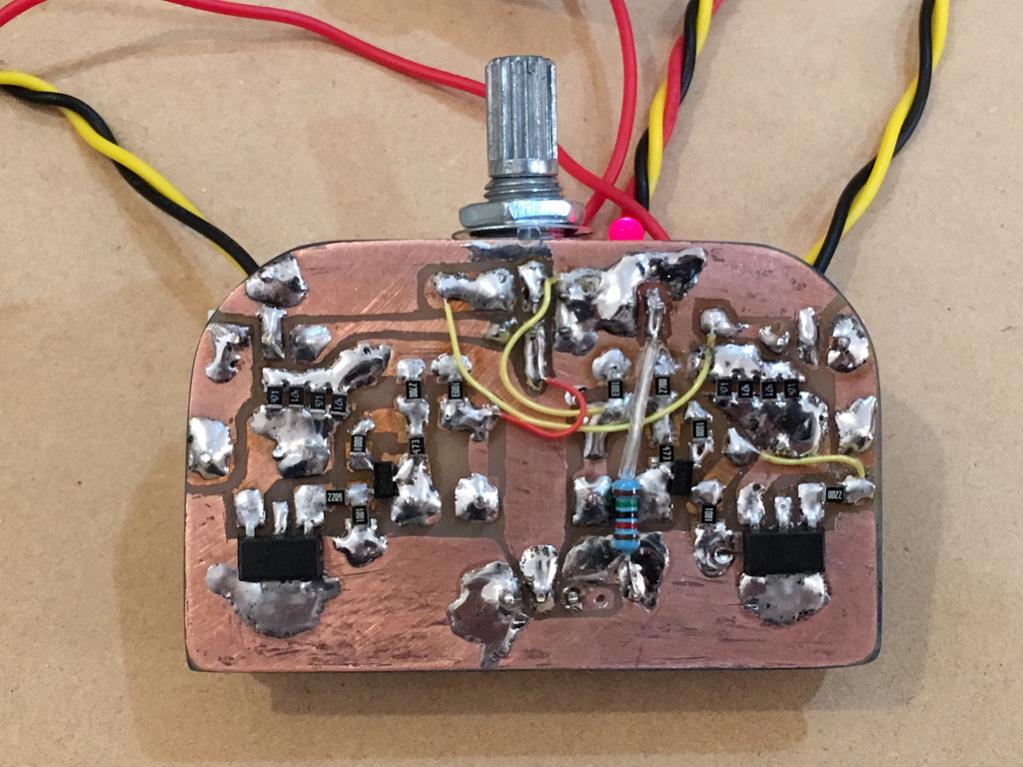
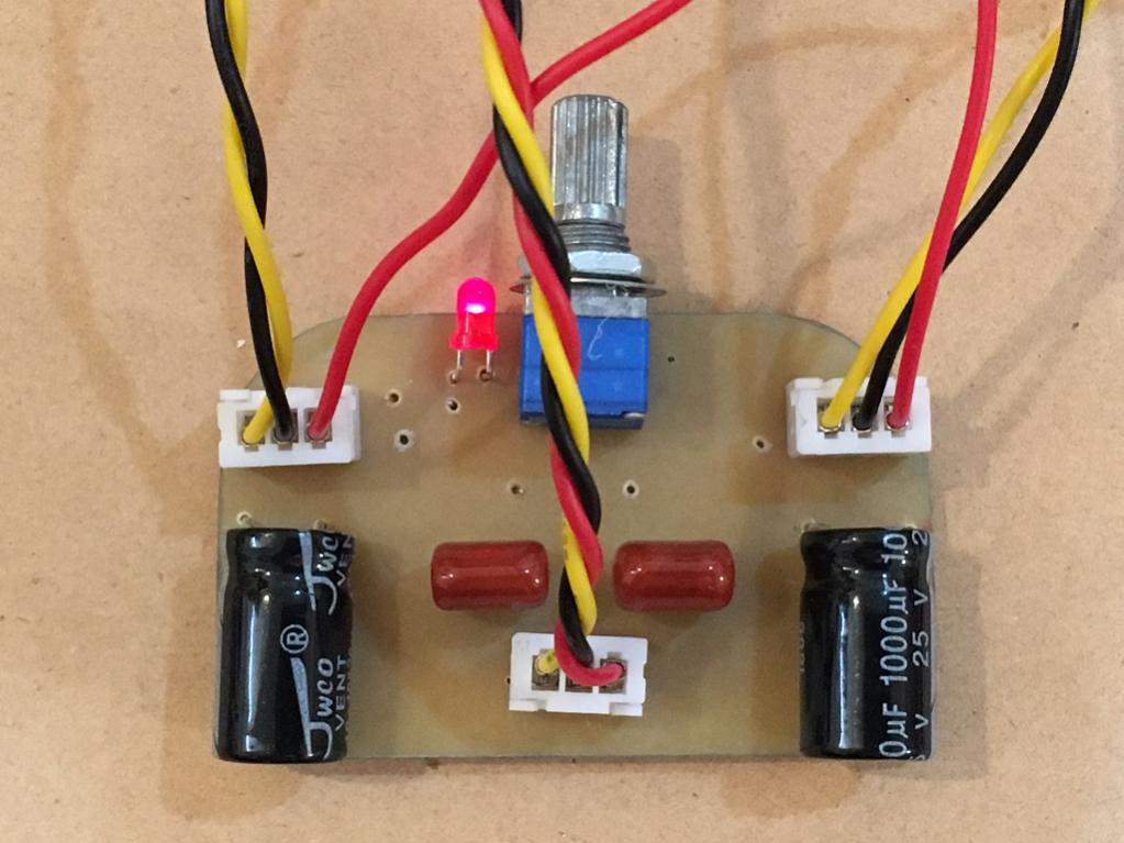
I added Vishay 0.47uF 100v MKP bypass output caps for added top end clarity; also added 2x 100uF 63v electrolytic power rail smoothing caps right next to MOSFET drain pins; added 100nF X7R bypass caps on MOSFET drain power rails; added 10uF 50v MLCC caps to the 1uF MKT input caps to get more bass extensuon; added 270R load resistors (shunts to ground) on outputs after coupling cap to load amp more and increase bass output and reduce HD (per sim of other similar amps - lower impedance than 250R brings HD down). Changes shown by red arrows.
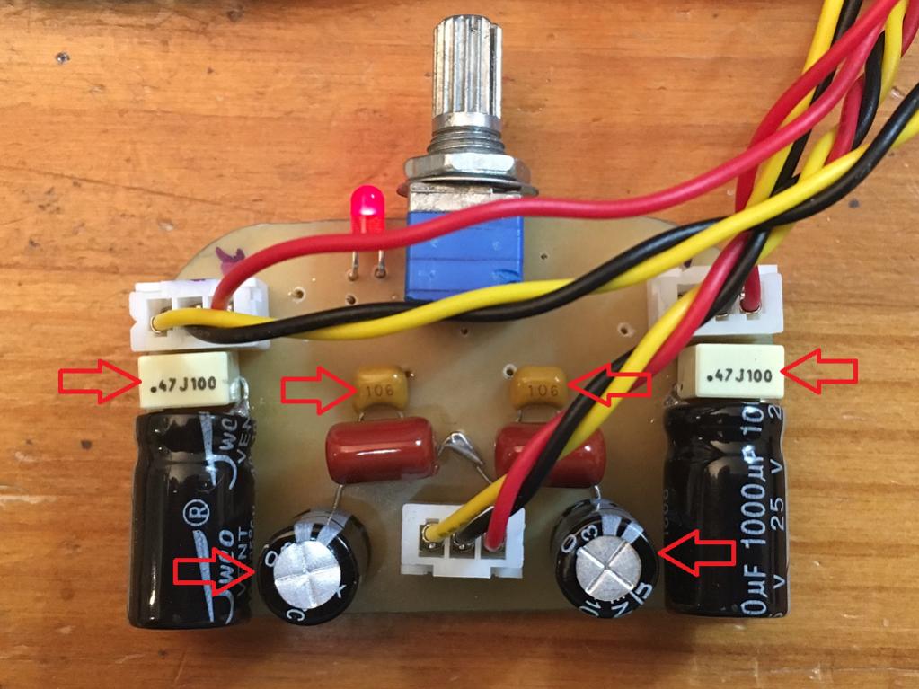

I have had a chance to listen to my usual suite of test tracks including jazz, female vocals, pop, deep house dance, rock, ... and this little guy just really suprises me! Puts a smile on my face and my feet start tapping. The mods helped the clarity and bass extension - very powerful bass beyond the little size would indicate. Absolutely low distortion and very pleasing harmonic profile. If I am right, there should be low amount of H2 and vanishingly small H3, and nothing else.
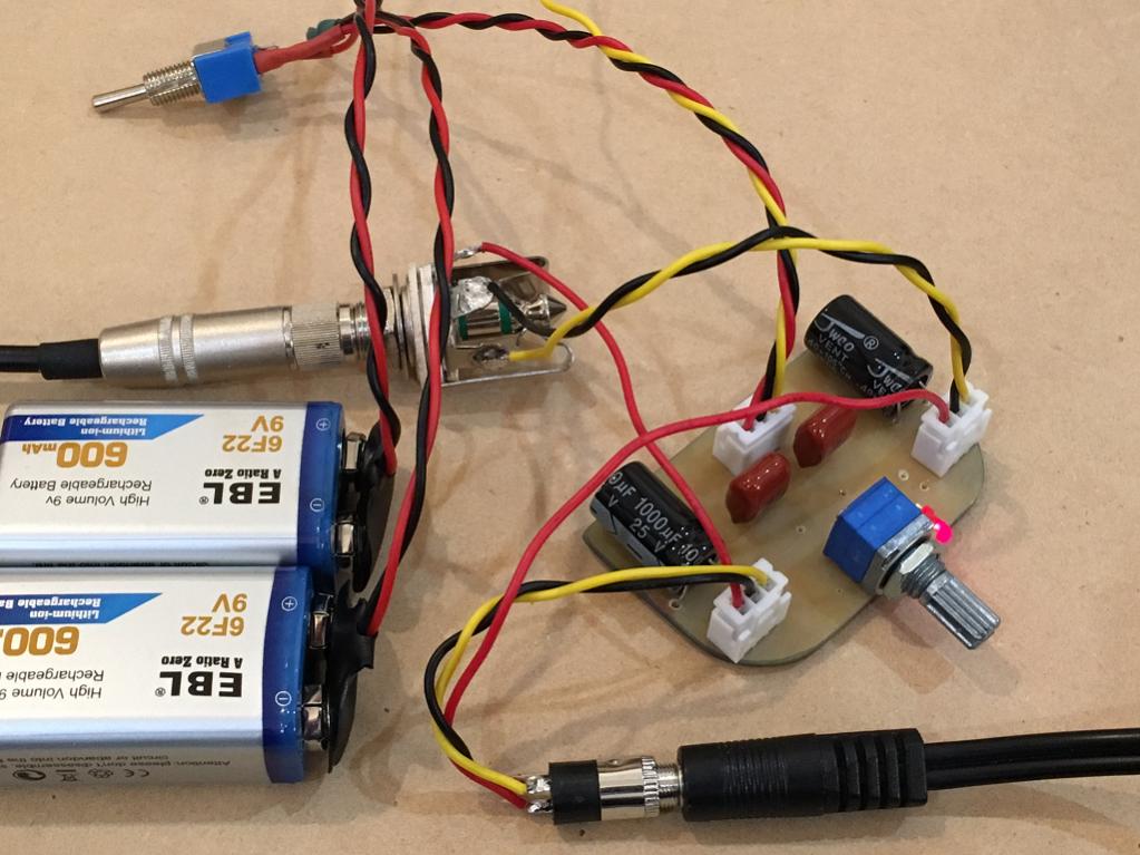
This amp is getting a case for sure. Well, it's just an Altoids tin for $1.67, so no biggie - but nice to have a pocket class A amp. Doubles as a hand warmer in this cold weather. 🙂
Awesome amp! Highly recommended.
I added Vishay 0.47uF 100v MKP bypass output caps for added top end clarity; also added 2x 100uF 63v electrolytic power rail smoothing caps right next to MOSFET drain pins; added 100nF X7R bypass caps on MOSFET drain power rails; added 10uF 50v MLCC caps to the 1uF MKT input caps to get more bass extensuon; added 270R load resistors (shunts to ground) on outputs after coupling cap to load amp more and increase bass output and reduce HD (per sim of other similar amps - lower impedance than 250R brings HD down). Changes shown by red arrows.
I have had a chance to listen to my usual suite of test tracks including jazz, female vocals, pop, deep house dance, rock, ... and this little guy just really suprises me! Puts a smile on my face and my feet start tapping. The mods helped the clarity and bass extension - very powerful bass beyond the little size would indicate. Absolutely low distortion and very pleasing harmonic profile. If I am right, there should be low amount of H2 and vanishingly small H3, and nothing else.
This amp is getting a case for sure. Well, it's just an Altoids tin for $1.67, so no biggie - but nice to have a pocket class A amp. Doubles as a hand warmer in this cold weather. 🙂
Awesome amp! Highly recommended.
Attachments


Last edited:
Hi X. First post for me. I've been watching your amp projects develop here and on your other thread. It's been cool to see you refine things in response to your own discoveries, as well from the info and advice contributed by the community. What an awesome process. Congrats on another success.
A portable Class A mint tin amp! Wow! I have very little experience with DIY audio (I have soldered a simple speaker crossover before) but I really want to have one of these amps! Once you have finalized your design, do you forsee creating detailed instructions, a BOM, and/or a printed circuit board for this build later on, similar to what Adgr has done with his Super CMOY?
By the way, how would you say the sound of your mint tin amp compares to the Super CMOY you built?
Hi Stellarelephant,
Welcome to DIYA! I am going to run a sim of this amp to see if I can tweak a little more performance out of it first. The amp actually is probably pretty close to ideal operating points. MOSFET gate voltage is about 8.2v and bias is 67mA. Input JFET bias is 8mA. It sounds wonderful. I don't do CAD layouts so someone else will have to help out for a real board we can send to a fabrication house. The BOM is pretty simple if you look at the schematic. Just a handful of resistors and caps and a JFET and a MOSFET. Let's see if someone can help with the layout and we can maybe do a group buy. I don't think I have seen another CMOY style mint tin amp that is SE Class A except for the one Easphyx was working on. But that one has 2 input JFETs and two output MOSFETs double the complexity.
http://www.diyaudio.com/forums/solid-state/298026-tin-fets-headphone-amplifier.html
Last edited:
I hadn't seen that other amp. Thanks for the link. Your simpler design sounds like a good fit for a newbie like me. Seems like yours could have longer battery life too. I'll stay tuned while you tinker and jump on the group buy when it comes. I think you've got a pretty unique little amp on your hands here...can't wait to build one and give it a listen!
It sounds wonderful. I don't do CAD layouts so someone else will have to help out for a real board we can send to a fabrication house.
Excellent work! PM reply sent. 😀
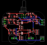
Very preliminary, but it's a start 😀.
Panasonic CS polymer input and output caps with 470nF bypass (but polyphenylene sulphide instead of MKP), 47uF smoothing ceramics with 100nF bypass, and output loading resistors.
I'm still a noob and I have no doubt that agdr has a better plan up the sleeve, so let's see what comes from that.
Panasonic CS polymer input and output caps with 470nF bypass (but polyphenylene sulphide instead of MKP), 47uF smoothing ceramics with 100nF bypass, and output loading resistors.
I'm still a noob and I have no doubt that agdr has a better plan up the sleeve, so let's see what comes from that.
Attachments
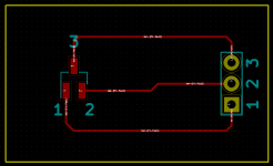
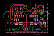
Thanks BDHM. You might want to look at my layout and follow it closely because it uses the larger copper plane on the end (1/3rd of the board) as a heatsink. Also the arrangement places the MOSFETs and the power resistors arrays at 4 corners to spread the heat. This board is pure class A and dissipates 18v x 140mA = 2.5w. Also, probably need to put through hole on one side like I did and mount board upside down like Agdr did. Need to use a pot with on off clicker. And maybe make room for PCB mounted 3.5mm jacks.
Thanks!
Cheers,
Thanks!
Cheers,
Last edited:
You might want to look at my layout and follow it closely because it uses the larger copper plane on the end (1/3rd of the board) as a heatsink. Also the arrangement places the MOSFETs and the power resistors arrays at 4 corners to spread the heat. This board is pure class A and dissipates 18v x 140mA = 2.5w.
I was going to add planes top and bottom with vias to spread heat, but I'll look closer at your design 🙂
Also, probably need to put through hole on one side like I did and mount board upside down like Agdr did.
The two big reservoir caps are on the opposite side

Will do!Need to use a pot with on off clicker. And maybe make room for PCB mounted 3.5mm jacks.
What were your PCB dimensions in the end? I used the same depth as the JDS Labs CMOYBB board, but it can't hurt to double check.
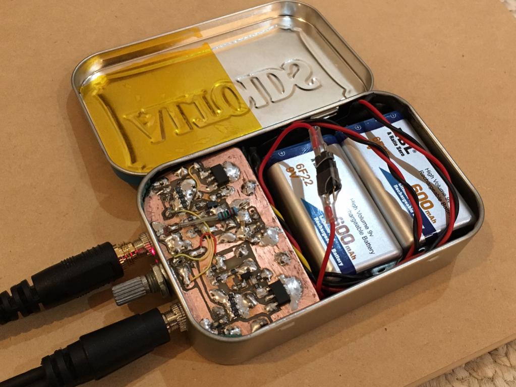
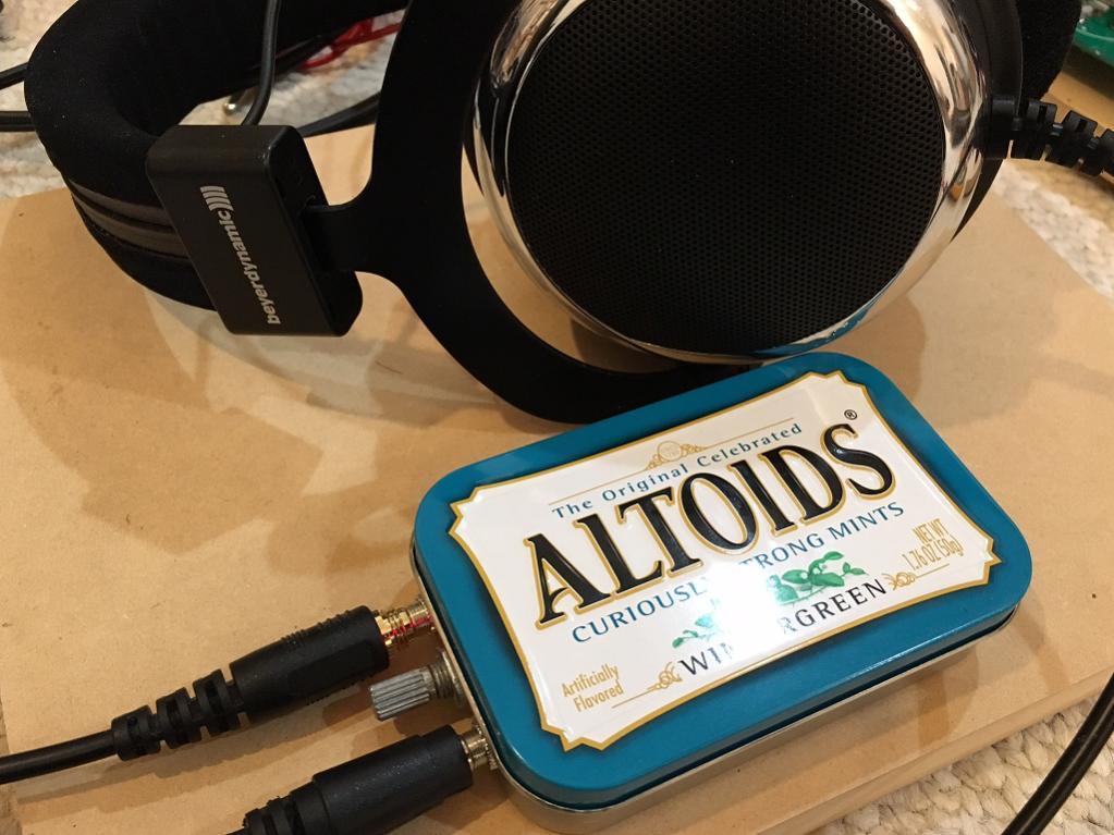
I am presently listening to this little guy on my morning bus commute - Paul Desmond's When Joanna Loved Me - pure heaven! Something about a nicely recorded jazz trio with sax, bass, and drums on a class A amp.
Awesome!Wintergreeen Class A Handwarmer 🙂
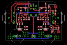
How is this looking?
Two images, one with ground and heatsink planes removed for clarity
Attachments
Hey that looks great! I've had the Monday morning realization that I just don't have time to layout anything else right now, but looks like you are well on the way. If there is a group buy, I'm in for one! 🙂
Better but you have both source resistors and MOSFETs next to each other and heat output will be pretty concentrated. I am testing in actual use now and my current setup is very good at spreading heat over entire board evenly. The resistors actually put out as much or more heat than MOSFETs.
I can touch the heatsink area next to MOSFETs for about 12 seconds before uncomfortable. That's probably circa 45deg C.
Notes:
1. Move 3.5mm jacks side by side next to pot just like mine to keep cables coming out from one end. Otherwise 90 degrees makes unwieldy and not pocket size with cords plugged in.
2. Reduce size of caps intruding into battery space or move them.
3. Use vertical space in box more - when mounting board upside down (good for heat dissipation - you have tons of room underneath. So use through hole elco caps with 90deg bent leads to fit.
4. Upside down board puts pot centerline and 3.5mm jacks at location on edge that doesn't interfere with lid closing.
5. Use qnty four source resistors to spread heat over larger surface area. Those are the hottest components! I use four 470R in parallel.
Thanks for doing this BDHM!
Your screen name makes me think of that disco song made famous on SNL🙂
http://youtu.be/HEXWRTEbj1I
Last edited:
Awesome!
How is this looking?
Two images, one with ground and heatsink planes removed for clarity
To me it seems not so practical to have in/out jacks on the opposite sides? Placing input, output and volume control together on a shorter side of the mint tin would probably be more convenient since it allows putting the headamp in a pocket while listening, otherwise cables sticking sidewise will not allow it, IMO.
I think I'll order something like this, price is 18£.
Is that just an adapter? Or a tester too? If adapter only that is pricey.
I got one of these testers and had SMT pad but doesn't measure Idss (at least as far as I know). You get Vgs (to single digit past decimal accuracy x.x ) though and was only $16. Also is handy LCR meter.
M328 LCD 12864 Transistor Tester DIY Kit Diode Triode Capacitance LCR ESR Meter | eBay

They're meant to be bent over, the intrusion won't happen then. Alas there's no way to tell Eagle that 😀2. Reduce size of caps intruding into battery space or move them.
Okie dokie. What is the internal height available in the tin?3. Use vertical space in box more
Hmm... perhaps larger TH resistors5. Use qnty four source resistors to spread heat over larger surface area. Those are the hottest components! I use four 470R in parallel.
 ? SMTs would be too low profile to make contact with the mint tin. Or heck, some Caddock thick film TO220s smashed in there!
Move 3.5mm jacks side by side next to pot just like mine to keep cables coming out from one end.
To me it seems not so practical to have in/out jacks on the opposite sides?
I was just gonna use right angle connectors 🙂. But sure thing, will move 'em. Before I do so, however, what connector should I implement? The footprint is currently for this one: https://www.sparkfun.com/products/8032 . I'm happy to change it there's a better alternative (preferably with an available Eagle lib)
A pleasure! I'll never be able to build one of these, but I find making layouts to be highly enjoyable. Kind if a zen thing.Thanks for doing this BDHM!
- Home
- Amplifiers
- Headphone Systems
- BF862 based SE Class A Headamp without the HEAT