What needs to change to drive a speaker? The idea of using *many* bf862 is attractive in a perverse way....
Last edited:
Uh oh... 😱
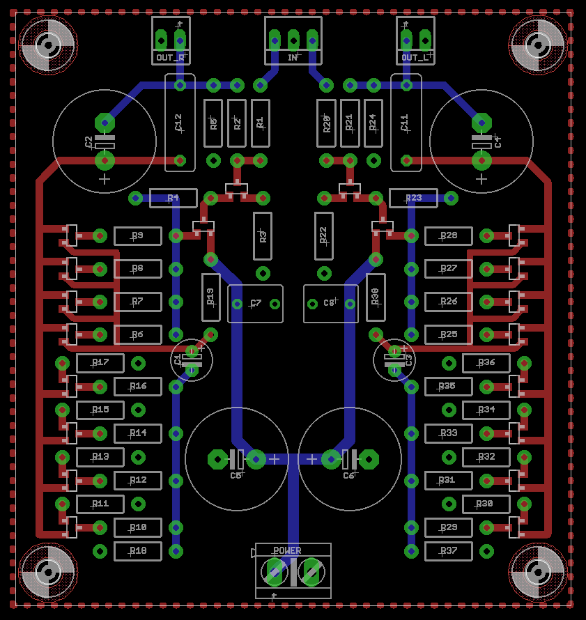
Any advice on my layout? Should I redo it non-mirrored?
Looks too NICE to change now. I wouldn't worry about. Build it! 🙂
Uh oh... 😱
Any advice on my layout? Should I redo it non-mirrored?
Inputs and outputs better be at different sides of the board. Easier mounting and easier wiring. Pads for volume control would be nice.
BF862 data sheet states that source and drain are interchangeable.
Is this actually the case, ie is every behaviour including noise perfectly symmetrical ?.
Dan.
Is this actually the case, ie is every behaviour including noise perfectly symmetrical ?.
Dan.
Inputs and outputs better be at different sides of the board. Easier mounting and easier wiring. Pads for volume control would be nice.
One other thing is if the JFET is already SMT, why make the resistors through hole? SMT resistors are much more compact, are better because they keep tracks shorter and easier and faster to install.
Any advice on my layout? Should I redo it non-mirrored?
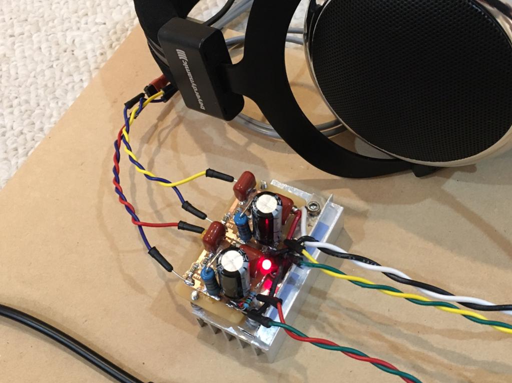
I think I see a film cap in parallel with the output blocking cap. Nice move.
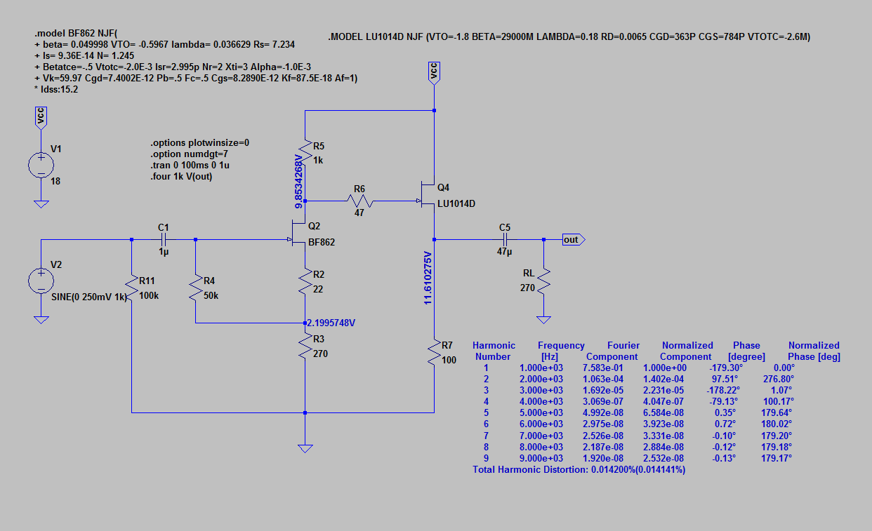
I recommend adding two small caps, one to the junction of R4-R9 and another at R23-R28. That will add a small RC filter which will help smooth the voltage to the first gain stage. It's easy, cheap, and I been doing that in the last few experiments. For sure it won't make things worse.
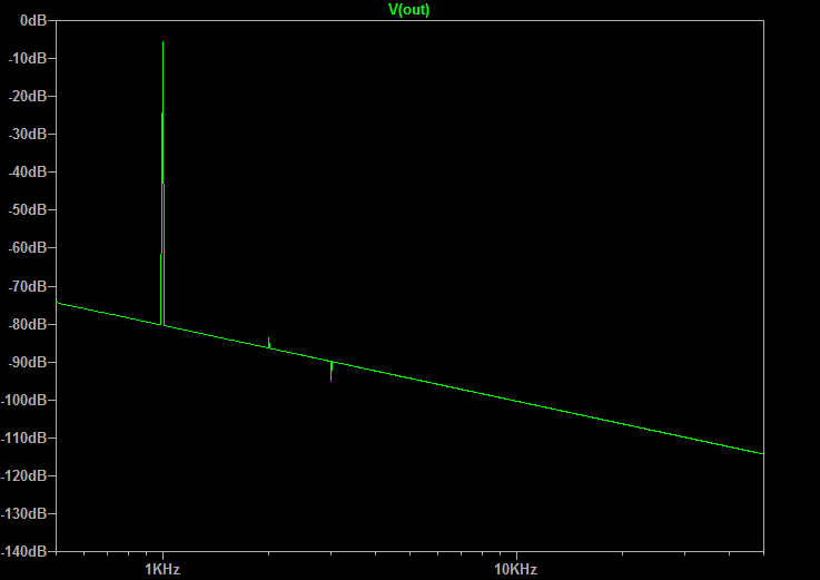
I had to change R4 and R23 to 10R. I originally used 20R (don't ask), using a 33R purely resistive load, but was seeing clipping starting at about 1V pp. Using EUVLs model, I was able to replicate the waveform by increasing those r values to about 100R, and then Vout voltage graph looked like the waveform on the scope. After reducing those from 20R to 10R the circuit will drive the same 33R load to about 10V pp before clipping, which is far more voltage than my lo-impedance headphones will ever need. The jfets measured 28 degrees C (give or take) during normal listening. Square waves are still very square at 100KHz and beyond.
I have not yet made up my mind about SQ. To me nothing sounds quite as musical as "the sound of one transistor clapping", but I keep trying anyway.
SMT resistors are much more compact, are better because they keep tracks shorter and easier and faster to install.
Not everyone is as excited about trying to solder SM resistors as you are.
Yes, they make for a much smaller board but they're not easier and faster to install compared to through-hole resistors.
For the lower dissipation resistors, you may be able to get by with .125W through-hole resistors making for a slightly smaller board, but I haven't done the math.
Is the output coupling cap 47uF or 470uF?
To me nothing sounds quite as musical as "the sound of one transistor clapping", but I keep trying anyway.
Care to elaborate more on your one transistor circuit?
I've tried quite a few simple preamp/buffer circuits with only 2 or 3 three transistors, but most sucked when it came to SQ.
Inputs and outputs better be at different sides of the board.
They don't have to be at opposite ends of the board. That's just your opinion.
He can easily move the outputs to the sides of the board as an option.
What's more important is he has the power input on the opposite of the board as the audio inputs and outputs.
That's exactly the way I would've done it.
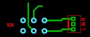
I would also add 6 extra pads for a dual volume pot as you suggested.
Attachments
Care to elaborate more on your one transistor circuit?
Post #1 in the following thread:
http://www.diyaudio.com/forums/headphone-systems/95841-mosfet-follower-headphone-amplifier.html
HE-560s and D2000s sound exceptionally good with that amp.
The thread (if you can follow it) contains a wealth of information, but it splits as it goes and then splits again... I don't think I've traced down each path to it's end. But there is some goof stuff in there I'd like to try in the next experiment.
Last edited:
So the circuit uses a MTP7N20E and a 1KuF output coupling cap in parallel with a 1uF MKT or MKP cap?
I'm not a big fan of AC-coupled circuits, but if you think it sounds pretty good I'm willing to give it a try.
I'm not a big fan of AC-coupled circuits, but if you think it sounds pretty good I'm willing to give it a try.
Sound of Two Transistors Clapping?
This is not quite 1 transistor but darn close. It's my current reference amp. Sounds fantastic. Design achieves remarkable transparency and bass authority.
http://www.diyaudio.com/forums/solid-state/301164-mosfet-source-follower-headamp-12.html#post4933130
Schematic:
FFT with 60ohm load at 1.2v p-p:
Core amp module (stereo):
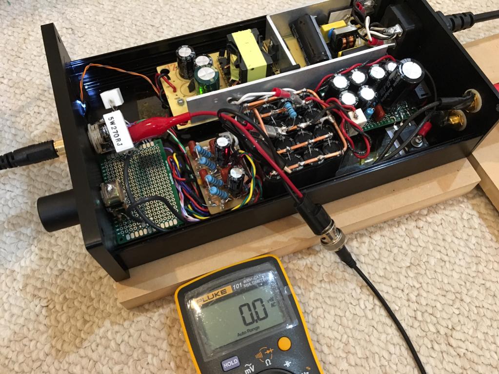
Boxed up output noise measurement:
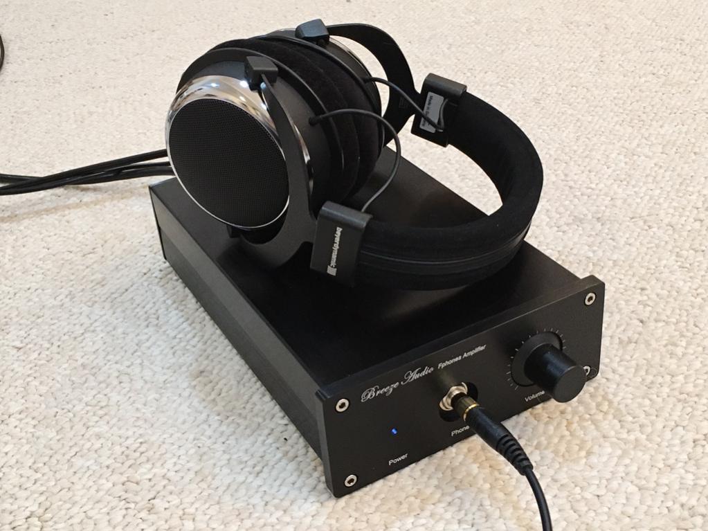
Final amp:
Care to elaborate more on your one transistor circuit?
I've tried quite a few simple preamp/buffer circuits with only 2 or 3 three transistors, but most sucked when it came to SQ.
This is not quite 1 transistor but darn close. It's my current reference amp. Sounds fantastic. Design achieves remarkable transparency and bass authority.
http://www.diyaudio.com/forums/solid-state/301164-mosfet-source-follower-headamp-12.html#post4933130
Schematic:
FFT with 60ohm load at 1.2v p-p:
Core amp module (stereo):
Boxed up output noise measurement:
Final amp:
So the circuit uses a MTP7N20E and a 1KuF output coupling cap in parallel with a 1uF MKT or MKP cap?
I'm not a big fan of AC-coupled circuits, but if you think it sounds pretty good I'm willing to give it a try.
Nor I. But I was bored just before the holidays and scrounged parts to build a proto. Strictly junk box and/or leftover parts. Nothing ordered.
I used a scrap piece of 3x4 perfboard, 2 ea IRF610 and 2 ea. heatsinks that were way too small. 2 ea. 100R 5W sand resistors. Finally 4 ea 470uf/16V bipolar caps, 2 in parallel for each channel. Now I'm afraid to take it apart.
There's only one sure way to find out if you will like it too.
This is not quite 1 transistor but darn close. It's my current reference amp. Sounds fantastic. Design achieves remarkable transparency and bass authority.
Will you post the .ASC file for your reference amp?
Very nice design!
How do you test for idss those smd parts(bf862) without soldering them?
Thanks
How do you test for idss those smd parts(bf862) without soldering them?
Thanks
Very nice design!
How do you test for idss those smd parts(bf862) without soldering them?
Thanks
This is for the multiple BF862 output amps. I did it initially as described by AKSA here:
http://www.diyaudio.com/forums/solid-state/301164-mosfet-source-follower-headamp-7.html#post4930568
and then later as described here:
http://www.diyaudio.com/forums/solid-state/301164-mosfet-source-follower-headamp-8.html#post4931004
I used the actual PCB and had a 1k Drain resistor fitted and temporarily jumpered the Gate and Source to ground. Applied 18v above the Drain resistor and measured the voltage at the Drain pin to get current through the 1k. Just press the SOT-23 package down with a plastic push stick to make contact and record measurement in 4 or 5 seconds so it doesn't heat up too much.
Will you post the .ASC file for your reference amp?
When I get to my LTSpice computer I can. It's simple enough you could just type in from screen shot.
Thank you for the input everyone 😀
EDIT: Wait, do you mean on the left and right sides?
Will do!Looks too NICE to change now. I wouldn't worry about. Build it! 🙂
I find it easier to mount the volume potentiometer on the front panel, hence the inputs and outputs on the same side of the board facing the front. I'll use shielded cable from the rear panel inputs to the pot.Inputs and outputs better be at different sides of the board. Easier mounting and easier wiring. Pads for volume control would be nice.
EDIT: Wait, do you mean on the left and right sides?
I'll give that a try 🙂. What sort value do you recommend?I recommend adding two small caps, one to the junction of R4-R9 and another at R23-R28.
I actually did a much smaller all-SMT layout for the fun of it, but I'd never be able to solder the darn thing. My hands are far too unsteady 🙁. The BF862s are going to be a real challenge. I may borrow a hot air station for this.Not everyone is as excited about trying to solder SM resistors as you are. Yes, they make for a much smaller board but they're not easier and faster to install compared to through-hole resistors.
1000uF with a 1uF film bypassIs the output coupling cap 47uF or 470uF?
- Home
- Amplifiers
- Headphone Systems
- BF862 based SE Class A Headamp without the HEAT