Spot on!
Attachments


Is that just an adapter? Or a tester too? If adapter only that is pricey.
I got one of these testers and had SMT pad but doesn't measure Idss (at least as far as I know). You get Vgs (to single digit past decimal accuracy x.x ) though and was only $16. Also is handy LCR meter.
M328 LCD 12864 Transistor Tester DIY Kit Diode Triode Capacitance LCR ESR Meter | eBay

It's only the adapter...
It's only the adapter...
For one of these very handy guys: Peak Electronic Design Limited - Atlas DCA Pro - Advanced Semiconductor Analyser - Model DCA75
Out of my budget alas 😉
BDHM,
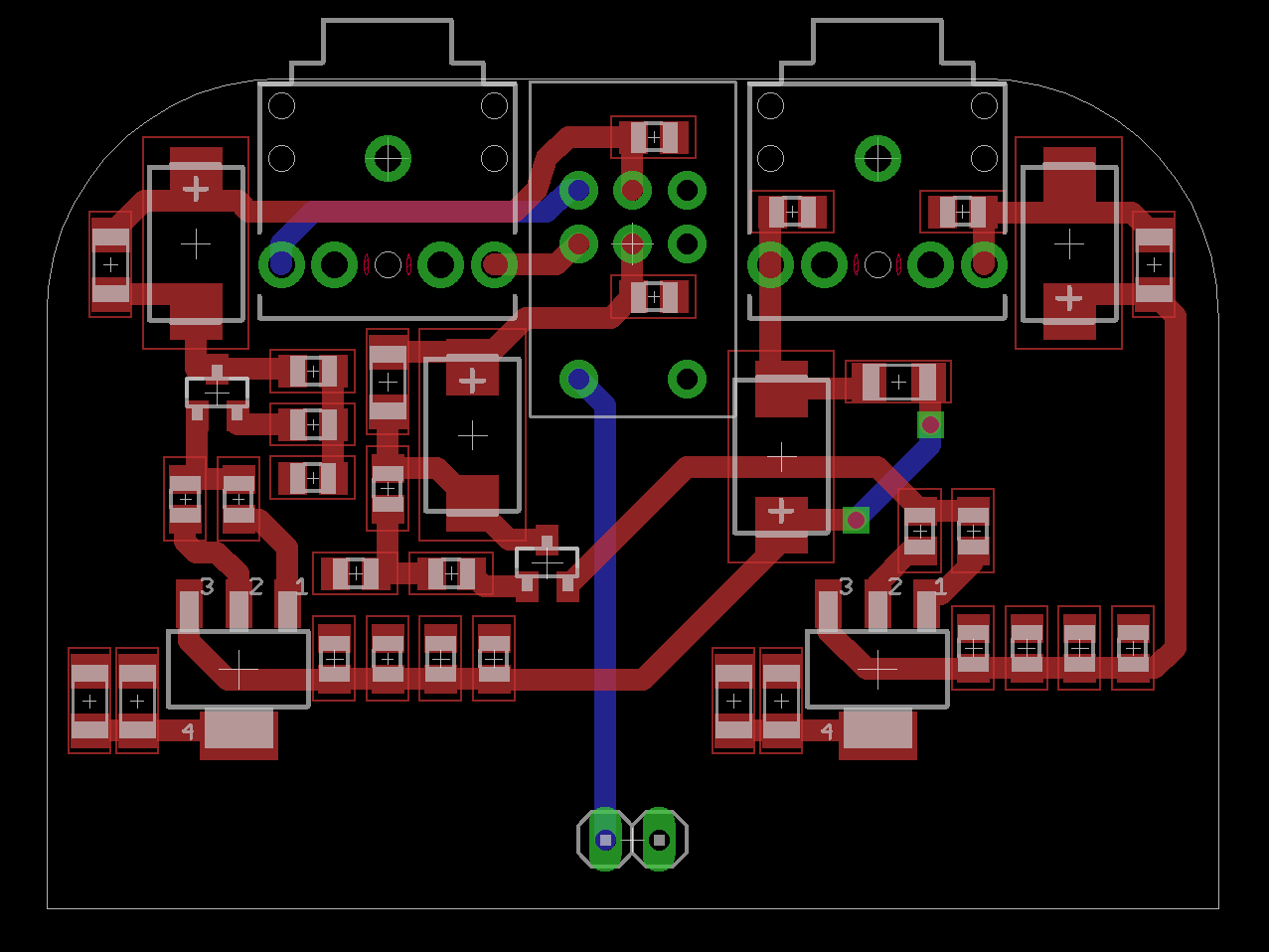
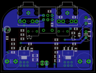
This is looking much better. The 3.5mm jacks look good here. Do you have provision for a power indicator LED? I use a little 3mm and 15k resistor from power rail. What size output electrolytic are you using? 470uF would be ideal to handle lower impedance headphones.
Maybe it's on different layer but why is gate of MOSFET connected to resistor tied to Drain? Only source of JFET should connect to Gate via gate stopper 220R. Not sure it matters but you may want to keep your positive supply rail for input stage away from drain pin on MOSFET but draw it from a low impedance power bus plane (the main heatsink area). Same with ground for input stage - should not run close to ground of MOSFET source resistors where large currents exist. If you noticed my layout, there is an attempt at a STAR ground emanating in middle of board to grounds for JFETs and MOSFET source resistor arrays. All these little details will reduce THD and IMD.
Thanks!
Last edited:
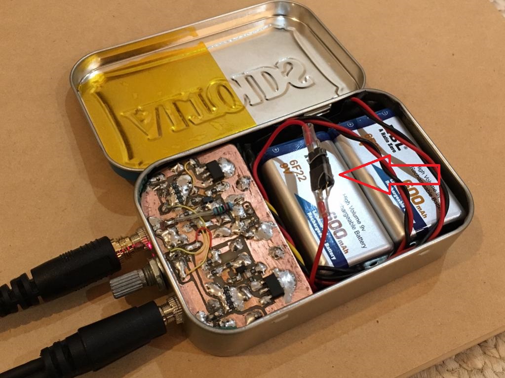
What's the battery run time ?.
Dan.
It's being tested today on my commute so I will confirm if it lasts at least 4 hrs. The rechargeable Li-ions that I have are EBL 600mAhr, at 150mAr with two cells in series for 18v, the estimate is 4hrs. One can reduce the bias to a more moderate 45mA and maybe JFET bias at 2mA and maybe get a little over 6hrs.
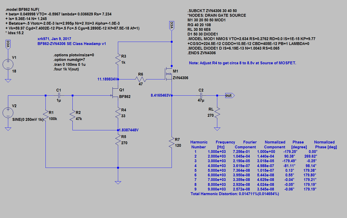
I just figured out how to import a third party model described as a ".subckt" into LTSpice - a major victory for me 🙂
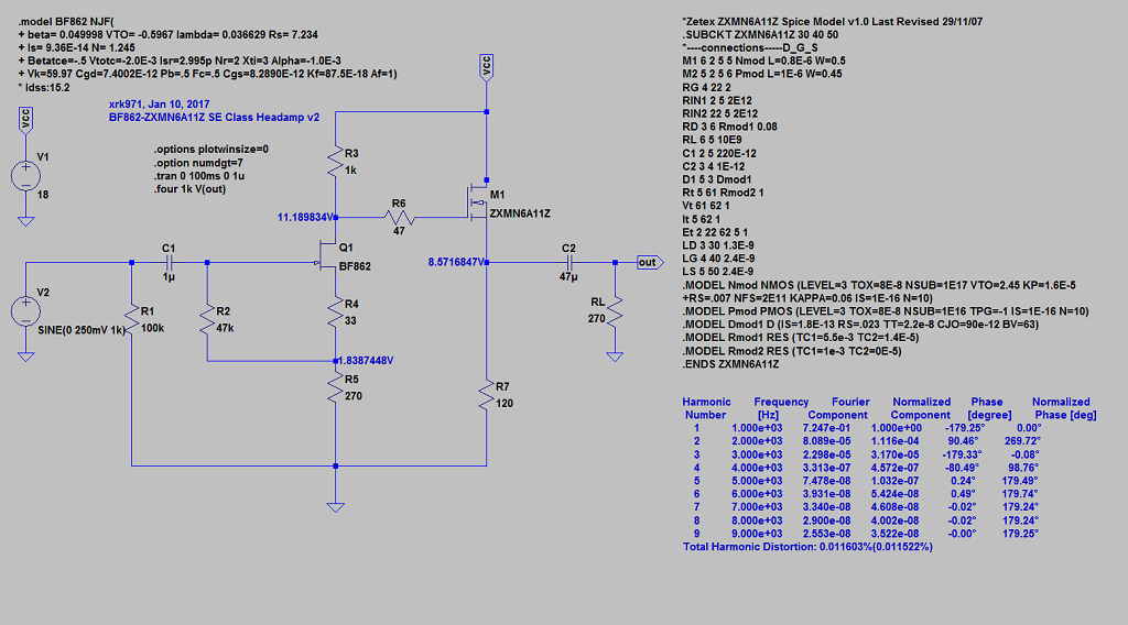
Here is the simulation with 1uF input cap and 47uF output cap. Note that BF862's can vary wildly and mine doesn't exactly match Idss predicted by model so you have to vary R4 to get the correct biasing through Q1, which then sets the correct gate voltage at M1. I found in the sim that having too large an output cap increase H3 vs H2, so if you want more pleasing sound, go with a lower value. I also found that gate stopper R6 doesn't have to be 220R but 47R works well too - should give better attack on percussives.
Here is schematic with THD analysis showing 0.014% THD with about 1.5v p-p output.
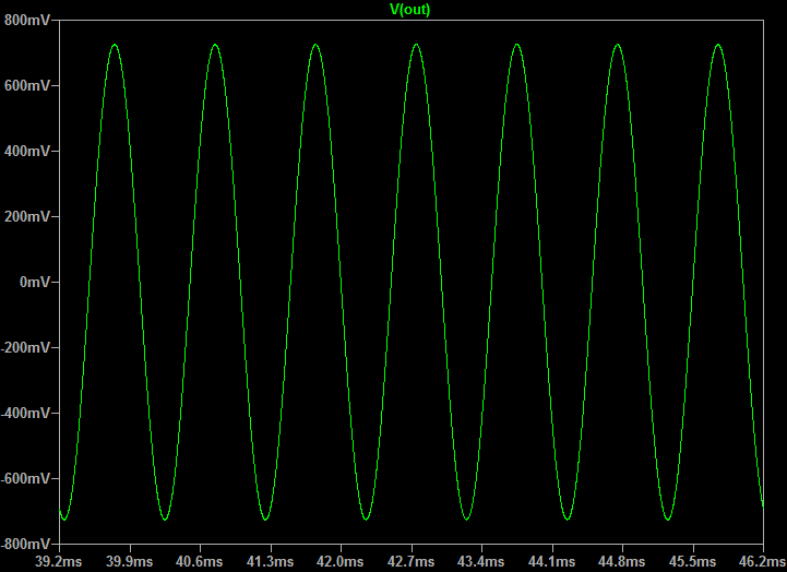
Here is nice 1kHz sine wave:
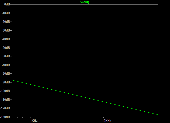
Here is FFT for 1kHz with 1.5v p-p output (note the low H2, and almost no H3, and nothing else - should sound great):
Here is the simulation with 1uF input cap and 47uF output cap. Note that BF862's can vary wildly and mine doesn't exactly match Idss predicted by model so you have to vary R4 to get the correct biasing through Q1, which then sets the correct gate voltage at M1. I found in the sim that having too large an output cap increase H3 vs H2, so if you want more pleasing sound, go with a lower value. I also found that gate stopper R6 doesn't have to be 220R but 47R works well too - should give better attack on percussives.
Here is schematic with THD analysis showing 0.014% THD with about 1.5v p-p output.
Here is nice 1kHz sine wave:
Here is FFT for 1kHz with 1.5v p-p output (note the low H2, and almost no H3, and nothing else - should sound great):
Attachments


They're meant to be bent over, the intrusion won't happen then. Alas there's no way to tell Eagle that 😀
Ok, got it - my recent sims show output caps should be 47uF and not 1000uF like I have.
Okie dokie. What is the internal height available in the tin?
Just measured it - 19mm is absolute max, leave a few mm for clearance with pins solder etc. so 17mm would be max with components mounted.
Hmm... perhaps larger TH resistors? SMTs would be too low profile to make contact with the mint tin. Or heck, some Caddock thick film TO220s smashed in there!
With upside down PCB (SMT's facing up I found that the radiation from the board to the lid (covered with Kapton tape) is sufficient to extract heat - no need for physical contact.
I was just gonna use right angle connectors 🙂. But sure thing, will move 'em. Before I do so, however, what connector should I implement? The footprint is currently for this one: https://www.sparkfun.com/products/8032 . I'm happy to change it there's a better alternative (preferably with an available Eagle lib)
Thanks.
I'll never be able to build one of these, but I find making layouts to be highly enjoyable. Kind if a zen thing.
Why would you say you will never build one? Soldering amps is very relaxing zen type of thing for me.
Last edited:
Added 🙂Do you have provision for a power indicator LED?
Originally, I used 47uF with a 470nf bypass. However, the Panasonic SP-CAPs in question go up to 100uF in that package, and much higher if lower voltages are suitable. What is the minimum voltage we should use here?What size output electrolytic are you using?
edit: As per post #129, 47uf was a good guess! I've now changed the input cap to 1uF, which means it's easy to fit a TH film cap there.
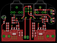
There's no connection there that I can seeMaybe it's on different layer but why is gate of MOSFET connected to resistor tied to Drain? Only source of JFET should connect to Gate via gate stopper 220R.
. It may appear that way in the image. I double checked the schematic and it's all good.Yup, I took this approach in earlier iterations. Going to have to do some wrangling for the latest one though.Not sure it matters but you may want to keep your positive supply rail for input stage away from drain pin on MOSFET but draw it from a low impedance power bus plane (the main heatsink area).
This is going to make things... interesting 😀. I'll see what I can do.a STAR ground emanating in middle of board to grounds for JFETs and MOSFET source resistor arrays.
I agree wholeheartedly, and I enjoy solder slingin' immensely. But my hands shake too much for anything on this scale. I'll likely throw an all-TH one together though. The ZVN4306 is available in TO-92, so it'll just be the BF862 that I need to struggle with.Why would you say you will never build one? Soldering amps is very relaxing zen type of thing for me.
It's being tested today on my commute so I will confirm if it lasts at least 4 hrs. The rechargeable Li-ions that I have are EBL 600mAhr, at 150mAr with two cells in series for 18v, the estimate is 4hrs. One can reduce the bias to a more moderate 45mA and maybe JFET bias at 2mA and maybe get a little over 6hrs.
I'm happy to report that the batteries lasted the full commute today with extra power to go. Still playing loudly after 3.5hrs usage today. 🙂
For one of these very handy guys: Peak Electronic Design Limited - Atlas DCA Pro - Advanced Semiconductor Analyser - Model DCA75
+1
But there are very good (perhaps better?) alternatives...
http://www.firstwatt.com/pdf/art_mos_test.pdf
Four hours is pretty decent! I noticed a few brands selling 9v batteries on Amazon that are rated for 800 mah. Perhaps a pair of these could yield 5 hours of blissful listening, if they live up to their claims...
For easy repeated charging, I started dreaming of ripping out the guts of a 9v charger and cramming that circuit in the tin, but by the looks of things, I doubt there'd be ample room. One option could be a couple of these curious-looking batteries--they have charging circuits built into them and micro USB ports on the bottom.
https://www.amazon.com/OKcell-Recha...UTF8&qid=1484021555&sr=8-3&keywords=800mah+9v
With a couple holes drilled in the tin, they'd charge from any USB device without even lifting the lid. It'd be even slicker if they'd both charge from one port, though. =)
I actually had a 2 position SPDT switch that could have been made to charge on the off position. Although since I am using a manual dual header pin connector it's easy enough to make a special charger if I can find a 5v or 12v based charger.
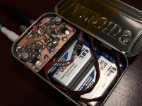
Based on results of the simulation, I removed the cheap 1000uF output elco and replaced with low ESR Panasonic 47uF 25v 551 PPF oscon cap. There was actually enough room on the SMT side to solder these low profile polymer caps in place. They also act as bumpers to prevent the live bate circuit board from touching the lid (if it were not already covered in Kapton tape). Still bypassed with 0.47uF 100v Vishay MKP. I removed the 10uF MLCC input coupling cap and just running 1uF 230v MKT cap. Listening now to tracks with very well known (to me) bass lines and kick drums and there is no lack of bass relative to previous setup. In fact, the percussive sharpness of the bass may have improved. More distinct bass. Clarity in highs appears to have increased as predicted by sim which shows higher distortion with larger cap values. I think the midrange is even better now. Very transparent and silky smooth. Little tweaks guided by simulation seems to have paid off.
New output caps
Here is the amp now with the 1000uF output caps removed, replaced with the Panasonic OSCON 47uF's. They are quite tiny and sound very very nice. I think the mids and highs sound even more clear now.

Here is the simulation with 47uF output cap and 1uF input cap again:
And here is predicted HD profile with this setup:
I had a thought today that if we make the PCB in a hybrid SMT and through hole for all non-actives, people might not be as intimidated to make this amp without worrying about soldering all those little resistors. It is simple enough that we may just have enough room. What do you all think?
Here is the amp now with the 1000uF output caps removed, replaced with the Panasonic OSCON 47uF's. They are quite tiny and sound very very nice. I think the mids and highs sound even more clear now.
Here is the simulation with 47uF output cap and 1uF input cap again:
And here is predicted HD profile with this setup:
I had a thought today that if we make the PCB in a hybrid SMT and through hole for all non-actives, people might not be as intimidated to make this amp without worrying about soldering all those little resistors. It is simple enough that we may just have enough room. What do you all think?
Attachments
Last edited:
I think I'll order something like this, price is 18£.
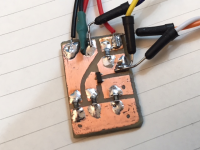
Here is my JFET tester - it measures the Ids at the specific operating condition set by the input stage circuit. I can also use an alligator clip to jump the gate to GND and measure Idss across the 1k Drain resistor. I can also jumper the pads to measure Vgs. With these three values, I can sort and bin to pretty nice groupings that should behave very closely. This little board is really easy to make with a Sharpie marker and then etch and solder on the resistors to match the circuit you plan to use it in. This gives you a perfect match of the Ids at the operating condition you are interested in. I only had time to do about 9 last night but of those 9, I found an almost perfect match for 3, so pretty good consistency on the same tape roll.

I bias it with two 9v batteries in series for 18v operating condition and use a DMM connected to one of the test leads of interest.
Attachments
Last edited:
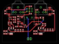
I think we're getting somewhere 🙂
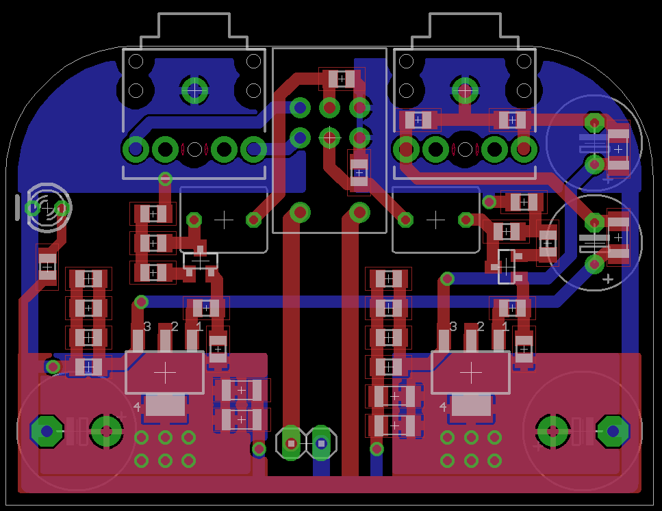
1uF TH film input caps, 47uF OSCON (20SEP47M) output caps with optional SMT film bypass (Panasonic ECPU would be a good option). The larger electro caps are power reservoirs, also optional as there are 47uF SMT caps with bypass already.
1uF TH film input caps, 47uF OSCON (20SEP47M) output caps with optional SMT film bypass (Panasonic ECPU would be a good option). The larger electro caps are power reservoirs, also optional as there are 47uF SMT caps with bypass already.
Attachments

Very nice work BDHM! 
Thanks!
Btw, I just ran a sim with ZXMN6A11ZTA (SOT89-3 package) and the distortion is even less - and Rdson is 1/3rd of ZVN4306 so should have more impactful bass even. I wonder if the pads are close enough one could use either?
Just checked data sheet, pads are indeed GDS, with D on 4th so should be compatible if spacing is correct.
ZXMN6A11ZTA Diodes Incorporated | Discrete Semiconductor Products | DigiKey
Last edited:
- Home
- Amplifiers
- Headphone Systems
- BF862 based SE Class A Headamp without the HEAT