Hi all:
I was interested in building a simple, nice-sounding, single op-amp per channel, MM phono preamp and the inside pics of the LFD LE phono stage posted on an online review caught my attention. Would anyone happen to have a schematic of a Bews NE5534-based phono preamp that they could share? I recall reading that his design is based off an older Hitachi circuit and thought it would make a nice first build. Many thanks for any and all help!
I was interested in building a simple, nice-sounding, single op-amp per channel, MM phono preamp and the inside pics of the LFD LE phono stage posted on an online review caught my attention. Would anyone happen to have a schematic of a Bews NE5534-based phono preamp that they could share? I recall reading that his design is based off an older Hitachi circuit and thought it would make a nice first build. Many thanks for any and all help!
Last edited:
Building a 1stage RIAA requires the feedback to define the RIAA curve and to provide all the gain.
This is not a great way to build a RIAA. It works at the OK level.
Better with at least two stages.
This is not a great way to build a RIAA. It works at the OK level.
Better with at least two stages.
Doug Self would disagree with you Andrew.
Don't know anything about a Bews amp, but Doug Self and John Linsley Hood have published single op-amp RIAA pre-amps.
Don't know anything about a Bews amp, but Doug Self and John Linsley Hood have published single op-amp RIAA pre-amps.
Last edited:
Building a 1stage RIAA requires the feedback to define the RIAA curve and to provide all the gain.
I see... so the precision of the RIAA could be altered? I suppose there could be overload problems as well with a single gain stage? Still, there might be something to be said for the simplicity of using a single op-amp in terms of build and sonics... evidence of the latter being the nice review of the LFD unit by Stereophile.
Doug Self and John Linsley Hood have published single op-amp RIAA pre-amps.
Thanks for the reply. Would you mind pointing out where I can find the Hood circuit diagram? Also, I assume the schematic by Self is in one of his texts?
I do not think so. Sure a single gain stage will work. I made one in college using a NE5533AN, it sounded okay, Doug did a singke gain stage in the '96 precision pre-amp. Since then look at the elektor pre-amp 2012, it's MM pre-amp is in 3 stages, RIAA( NE5534A with some gain), LPF, adjustable gain stage using LM4562's.Doug Self would disagree with you Andrew.
It is a well known fact that if you split an opamp gain into two or more devices, the over all distortion is less. There are other benefits too except cost and pcb area.
Got to like some one getting this $ for a NE5534 based phono amp
At the same time, LFD has no particular fear of op-amps, a stereo pair of which is used in the product under review: the Phonostage LE ($1295). According to Richard Bews, the NE5534 op-amp chip that provides voltage gain in the Phonostage LE was chosen specifically for its sound quality—and because it can be used to produce the desired DC offset for biasing the preamp's output-coupling capacitor. At the input end, a high-end Beyschlag resistor establishes the cartridge load, while the RIAA equalization network uses new-old-stock Bayer/WIMA polycarbonate capacitors. LFD apparently had the good sense to squirrel away those parts over the years: shades of Shindo.
WOW all for ($1295) = nutsthe LFD Phonostage is indeed as minimalist as they come: 28 resistors, 24 capacitors, 4 regulators, 2 epoxy diodes, 2 op-amp chips, and 1 transformer,
Last edited:
To quote Doug in the Preamplifier 2012(2) article
I like this one
My previous preamp designs have used a single stage version of this, but I have found the
two-stage configuration is preferred when seeking the best possible distortion performance
I like this one
Say what 🙂 Anyone care to explain this for me?It was, in fact, from one of the papers Dr. Hawksford delivered to the AES that LFD got its name: Low Fuzzy Distortion (footnote 1). (In this context, fuzzy means random, though that's not to say the more common definition might not also apply.)
Last edited:
Building a 1stage RIAA requires the feedback to define the RIAA curve and to provide all the gain.
This is not a great way to build a RIAA. It works at the OK level.
Better with at least two stages.
No - when using opamps, single stage is the way to go.
1. Best overload capability
2. Best noise performance
Last edited:
See post # 5 of this thread for a 1 stage op amp riaa 50x gain stage. http://www.diyaudio.com/forums/anal...improving-disco-mixer-mid-fi-performance.html
I used St33078 IC finally. I don't think my supplier had 8 pin dip 5532 at that time. 4558 op amp as OEM on the Herald RA-88a is hissy. The upgraded circuit sounds okay, excepting a tiny bit of hum. Hum is not the RIAA stage fault, something about power supply I imagine. Just using it, bought .0033 uf film caps to replaced the ceramic roll off caps but never installed them. I'm not annoyed enough about the sound of the appliance to work on it with other broken equipment laying around. The PAS2 preamp I own sounds actually worse with .02 uf mylar caps instead of .022 uf paper; that used to be a legendary product until a paper cap wandered off value after 50 years.
I used St33078 IC finally. I don't think my supplier had 8 pin dip 5532 at that time. 4558 op amp as OEM on the Herald RA-88a is hissy. The upgraded circuit sounds okay, excepting a tiny bit of hum. Hum is not the RIAA stage fault, something about power supply I imagine. Just using it, bought .0033 uf film caps to replaced the ceramic roll off caps but never installed them. I'm not annoyed enough about the sound of the appliance to work on it with other broken equipment laying around. The PAS2 preamp I own sounds actually worse with .02 uf mylar caps instead of .022 uf paper; that used to be a legendary product until a paper cap wandered off value after 50 years.
there are some mcintosh preamp schematics available via google that feature single gain stage designs using the NE5534A.
not state of the art and no exotic parts, but would likely be just fine for your needs.
a decent power supply would be a nice touch.
good luck,
mlloyd1
not state of the art and no exotic parts, but would likely be just fine for your needs.
a decent power supply would be a nice touch.
good luck,
mlloyd1
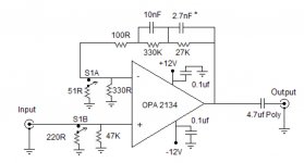
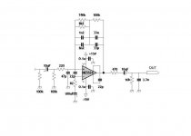
Hi All. I have found a single stage using Burr Brown 2134s to work quite well. With clean power you can get huge S/N ratios and the RIAA compensation is quite accurate. Distortion at the various points I checked (with an HP distortion analyzer) was below 0.08%. I did intentionally limit the gain for LOMC at 55 db ( MM is at about 38db) over concerns that you might run into a gain - bandwidth issue at the top of the audio band. BTW I was unable to see that in scope traces even when the output was driven to +/- 5VRMS. I notice that there are now some newer audio ICs that seem to have lower distortion than the 2134s and I would suspect that a nice sounding preamp could be made with them. As always YMMV, I just figure that with fewer components in the mix...there is less chance of altering the signal.
there are some mcintosh preamp schematics available via google that feature single gain stage designs using the NE5534A.
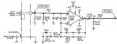
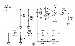
Thank you for mentioning that. I used to have a C35 that had a rather nice phono section. As you mentioned, not cutting edge, but better than any sub $300 phono amp I've played with. I looked at the schematics for a C34V and C35 (RIAA shown) and they indeed both use NE5534s. Any comments on either diagram? As shown would you expect them provide 35-40dB of gain?
Attachments
Hi All. I have found a single stage using Burr Brown 2134s to work quite well...
...I just figure that with fewer components in the mix...there is less chance of altering the signal.
Thank you for your reply. Less components = less degradation: That's kind of what I was hoping...
Do you happen to have a nicely detailed schematic for the OPA2134 -based MM phono pre you describe? 😀 Sounds like it works quite well.
Both those circuits using a non inverting topology have a minimum gain of 1.
That ruins the HF response.
The final 75us roll off should be a passive filter and preferably after the active stage output if one uses a non inverting arrangement.
That ruins the HF response.
The final 75us roll off should be a passive filter and preferably after the active stage output if one uses a non inverting arrangement.
Last edited:
Hi All. I have found a single stage using Burr Brown 2134s to work quite well.
Hi Bruce, Is this the phono pre you were referring to? Thanks!
Attachments
The final 75us roll off should be a passive filter and preferably after the active stage output if one uses a non inverting arrangement.
Hi Andrew: Sorry for asking you to get in the head of the previous designer, but do you feel there is any advantage to the shown RIAA layouts? Thanks!
The C35 preamp circuit looks similar to the Herald R-88a op amp circuit which I think sounds fine on my piano source component test. I have a Steinway console between the speakers for reference to CD source reproduction. The herald mixer uses 100k across the .033 uf instead of 95.8 k. Mcintosh probably had a $4 1% capacitor, too.
As any HF loss, my ears roll off at 14 khz as do my SP2-XT speakers. If Andrew can hear 14 khz to 20 khz he is a very unusual adult male- I've worn ear protection since ROTC camp 1969 at the rifle range, in industry and using power equipment. My hearing was last tested in 2008 when I was working maintenance .
Any of these circuits will work with most op amps, the 5534 has a wierd pinout I believe. The C35 pinout is certainly weird coming out pin 6 and going in 3, 2. That is the single op amp pinout, and music somes in stereo. Most dual DIP op amps go in 3,2, out 1, in 5,6, out 7. ST33078 is a lot cheaper than OPA anything, and sounds really good for $.37 each. Another low price low noise op amp is njm2043. If you put in a socket you can swap around. I bought some LM4562 but didn't bother to install them; why dink with good sound from the RA-88a mixer when my power amp is roasting output transistors and my tube amp is blowing the fuse with new tubes and e-caps.
All the fast op amps, slew rate >2 v/microsec, need a 33 pf disk cap across the feedback components to kill high frequency oscillations. As proved in my 4558 to 33078 experiment. That is from output to inverting imput. Kills ultrasound gain. Also, a .1 disk cap across rails within an inch of the package. I'm getting away with one power supply disk cap for 2 DIP op amp packages, and not bypassing power to the analog ground. Only 2 holes drilled in the PC board.
Last edited:
I would have to ask myself, if that 100pF across the +IN & -IN does anything for the 75us roll off? But I don't know the answer.Hi Andrew: Sorry for asking you to get in the head of the previous designer, but do you feel there is any advantage to the shown RIAA layouts? Thanks!
use LT SPICE or something similar to know for sure.
🙂
AndrewT is correct about the frequency response correction. however, there is sometimes dispute as to whether it matters audibly or not. did you cut those schematics a little prematurely? it's been a LONG time since i looked at those, but I "thought" they had a passive LPF after the opamp somewhere...
at any rate, you can go to the analog devices website and download the opamp handbook (i think it is chapter 6). LOTS of good info in there on RIAA preamps using opamps, including the corrective filter after the preamp. strongly recommended very worthwhile reading before building anything.
good luck,
mlloyd1
...As shown would you expect them provide 35-40dB of gain?
- Status
- Not open for further replies.
- Home
- Source & Line
- Analogue Source
- Bews NE5534 phono preamp