If I hard-wire for triode operation, I would conceivably reduce the proposed 600-Ohm 6550 Individual Cathode Resistors down to 525-Ohms, as per the 6550 Datasheet recommendations for triode operation.
Perhaps even 500-Ohms - as the current Cathode Bias is approximately 375-Ohms; a half-share of the original shared 750-Ohms.
Correction: The current Shared Cathode Bias resistor for each 6550 pair is 375-Ohms. So presumably, each 6550 is getting around half of that... Quite low, compared with the 6550 Datasheet, but until I can measure other aspects of the current 6550 handling - to provide a reference point - this data remains a bit meaningless.
On to the mapping and measuring...
cathode resistors are chosen on the basis of desired cathode currents consistent with the plate dissipation ratings of the tube...at the 6550 plate voltage....
Last edited:
I understand.
As above, I am now moving-on to mapping and measuring BEWITCH, to better understand what is actually happening in this particular circuit.
Moving forward, this mapping and measuring will help me make decisions around suitable cathode resistor values, etc.
I'm slowly getting there. 😀
As above, I am now moving-on to mapping and measuring BEWITCH, to better understand what is actually happening in this particular circuit.
Moving forward, this mapping and measuring will help me make decisions around suitable cathode resistor values, etc.
I'm slowly getting there. 😀
two 20k resistors replaced with 10k.....
the two paralelled resistors can dissipate more heat, i do that all the time, than simply a single resistors.....
there are reasons why things are done the way they did...
the two paralelled resistors can dissipate more heat, i do that all the time, than simply a single resistors.....
there are reasons why things are done the way they did...
Last edited:
Thanks TonyTecson. Yes. I understand.
The point I mention it is... the amp schematic shows two 20K resistors in parallel, bUt the amp factory build shows one 10K resistor. So it is the factory that made the change.
Easily fixed by fitting a much higher wattage resistor in the 10K position - which is what I have done. I went with a cheap, non-magnetic 10K / 4W wirewound.
I will check to see what else the factory has changed, from the published schematic.
Last edited:
happens a lot at the factory depending on material availability...
me too seldom follow any schematic to the letter....i deviate too....
you can measure the actual voltage across that 10k resistor and get the actual dissipation in watts, so if 100 volts is dropped across those resistors, then actual dissipation is 1 watt, so 4 watts or even 5 watts is good to use....
...it appears that the two paralleled 20K resistors, have been replaced with individual 10K resistors. [I need to confirm how the schematic has changed in this regard - and if the two 6N8P tubes are still connected - but there are no 20K resistors anywhere in the amp; and two 10K resistors that were not mentioned at all on the schematic...]
.
I was wrong about this.
There are two 18K resistors in parallel, serving in the R6/R7 positions, shown on the factory schematic.
The 10K resistors mentioned above are in a different position.
Still mapping...
Agreed.
I only wish that amp manufacturers printed component naming (C3, R1, etc.) on the actual PCB!
Mapping the populated PCB - back to the schematic - is a bit like trying to unravel an Agatha Christie mystery.
Definitely not for the faint-hearted.
(Clearly reflecting my newbie status...)
I only wish that amp manufacturers printed component naming (C3, R1, etc.) on the actual PCB!
Mapping the populated PCB - back to the schematic - is a bit like trying to unravel an Agatha Christie mystery.
Definitely not for the faint-hearted.
(Clearly reflecting my newbie status...)
Last edited:
the fun part of it is when you are able to follow schematics as it applied to the actual pcb....you learn better that way...
@johnss
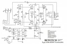
If you are willing to share your BEWITCH Schematic, I would be grateful.
I would be interested to see how it compares - at all - to the BEWITCH Schematic that I have already shared.
Appreciated.
If you are willing to share your BEWITCH Schematic, I would be grateful.
I would be interested to see how it compares - at all - to the BEWITCH Schematic that I have already shared.
Appreciated.
MILLS 12W Resistors into Shared Cathode Resistor Position...
@johnss
@TonyTecson
My schematic "mapping" task continues, assisted greatly by johnss sharing photos of his BEWITCH 6550, which has PCB tracks highlighted in orange. (Mine does not!) Thanks again John. This has made everything so much easier.
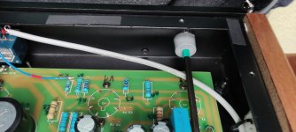
As suggested a while back by TonyTecson, I removed the TRIODE/UL switches and hardwired our BEWITCH 6550 for TRIODE operation only. A side benefit of losing the switches, is that I can lift the main PCB very quickly, without needing to fiddle with the switch wires. This is a huge advantage, because I am trying to perform changes in isolation to determine the impact; and learn. The TRIODE output is plenty for our 93dB sensitive 08-Ohms speakers.
I subsequently changed a number of the the factory resistors to non-magnetic, 4W wirewound types - and our BEWITCH took another good step forward in sound quality. This sonic step forward did NOT happen immediately though. After the change, the amp sounded pretty dreadful for the first few hours; and then slowly came on-song. It was worth the wait and we have been enjoying the amp for several weeks, based purely upon these changes. I'd wager that many listeners would have been happy enough to stop there and do no more to improve the amp.
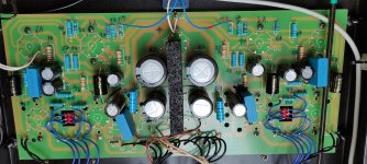
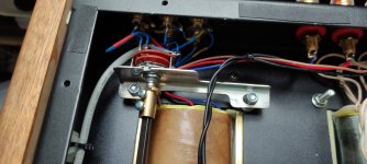
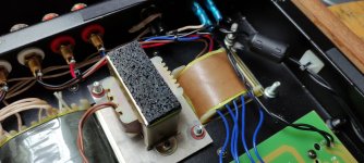
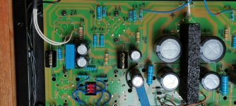
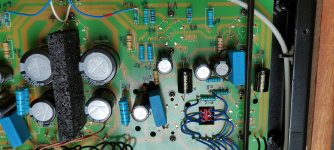
But more parts finally arrived from the UK - HIFI COLLECTIVE - and I was finally able to see what a quad of matched MILLS 12W non-magnetic resistors could bring to the table - if anything at all? - in the 6550 Shared Cathode Resistor position.
[02 x 750-Ohm paralleled to deliver 375-Ohms/24W Power Handling, per side...]
I made the changes last night and my wife and I sat down for a serious listen after 60-minutes of burn-in. To say that we were a bit overwhelmed is an understatement. WHAT A TRANSFORMATION! I heard brand-new things in albums that I have been listening to for 40-years! My wife's favorite test tracks sang-out like never before. OPENESS and CLARITY took a massive step forward, accompanied by an alluring sonic refinement and "softness" to the sound, that is quite difficult to put into words. My wife summed it up best, when she described that there was a much greater sense of "ease" and "flow" to all the music we played. The real test was the fact that enjoyment levels have skyrocketed and it is now quite hard to drag ourselves away from the listening chair. The fact is, that even albums that I am heartily sick-off, are now an absolute revelation!
I appreciate that all of this stuff is very highly subjective - and probably won't pass muster with the measurements brigade - but I wanted to share what I'm learning as others have been so generous with sharing their expertise.
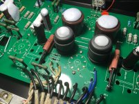
I have provided a few pics of how things are looking under the hood of the BEWITCH.
I'm probably not going to bother trying to implement Individual Cathode Bias resistors for each 6550. With 24W of power handling per side, I feel that the amp is safe and sound.
But I am really looking forward to hearing what the other premium resistors I have purchased, can deliver to this amp!
I will continue to report.
@johnss
@TonyTecson
My schematic "mapping" task continues, assisted greatly by johnss sharing photos of his BEWITCH 6550, which has PCB tracks highlighted in orange. (Mine does not!) Thanks again John. This has made everything so much easier.
As suggested a while back by TonyTecson, I removed the TRIODE/UL switches and hardwired our BEWITCH 6550 for TRIODE operation only. A side benefit of losing the switches, is that I can lift the main PCB very quickly, without needing to fiddle with the switch wires. This is a huge advantage, because I am trying to perform changes in isolation to determine the impact; and learn. The TRIODE output is plenty for our 93dB sensitive 08-Ohms speakers.
I subsequently changed a number of the the factory resistors to non-magnetic, 4W wirewound types - and our BEWITCH took another good step forward in sound quality. This sonic step forward did NOT happen immediately though. After the change, the amp sounded pretty dreadful for the first few hours; and then slowly came on-song. It was worth the wait and we have been enjoying the amp for several weeks, based purely upon these changes. I'd wager that many listeners would have been happy enough to stop there and do no more to improve the amp.
But more parts finally arrived from the UK - HIFI COLLECTIVE - and I was finally able to see what a quad of matched MILLS 12W non-magnetic resistors could bring to the table - if anything at all? - in the 6550 Shared Cathode Resistor position.
[02 x 750-Ohm paralleled to deliver 375-Ohms/24W Power Handling, per side...]
I made the changes last night and my wife and I sat down for a serious listen after 60-minutes of burn-in. To say that we were a bit overwhelmed is an understatement. WHAT A TRANSFORMATION! I heard brand-new things in albums that I have been listening to for 40-years! My wife's favorite test tracks sang-out like never before. OPENESS and CLARITY took a massive step forward, accompanied by an alluring sonic refinement and "softness" to the sound, that is quite difficult to put into words. My wife summed it up best, when she described that there was a much greater sense of "ease" and "flow" to all the music we played. The real test was the fact that enjoyment levels have skyrocketed and it is now quite hard to drag ourselves away from the listening chair. The fact is, that even albums that I am heartily sick-off, are now an absolute revelation!
I appreciate that all of this stuff is very highly subjective - and probably won't pass muster with the measurements brigade - but I wanted to share what I'm learning as others have been so generous with sharing their expertise.
I have provided a few pics of how things are looking under the hood of the BEWITCH.
I'm probably not going to bother trying to implement Individual Cathode Bias resistors for each 6550. With 24W of power handling per side, I feel that the amp is safe and sound.
But I am really looking forward to hearing what the other premium resistors I have purchased, can deliver to this amp!
I will continue to report.
Attachments

Last edited:
Hello SONDEKNZ
and others
Bewitch 6550/KT88 owner!
i am trying to write here with the help of google translate, hope understand me !!
I worked on the design of my Bewitch 6550 (bought in 2017 and had it come from China) a year ago or made changes externally.
(do you say facelift or?)
http://www.hifi-forum.de/index.php?action=browseT&forum_id=111&thread=4974&postID=728#728
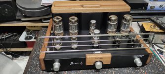
So, get to work, there was a nice wooden plate made of mahogany and also some chrome dividers from the store shelving system that I was allowed to take with me, otherwise it would have ended up in the container.
And after almost two days of working on the wooden parts, the beautiful applications were finally attached to the device, on the front and the sides are glued, and on top the wooden top plate
(on the transformer cover) are glued with 2 embedded magnets.
The chrome tube protection at the front, even matching with wood, was optically very pleasing, I have to say it was worth the work on it, optically I like the device even better and it looks noble.
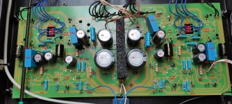
A few weeks ago the tube amplifier was open and finally modified internally, although only in crucial places where something really brings sound advantages.
All resistances are replaced by blue ones with 1%, several MKPs foils 0.68uF in addition to voltage capacitors and line filters, what was important for me was the change at the cinch input through better cabling and switching takes place directly at the inputs.
At the same time I took the circuit diagram created by Bewicht to hand and compared it with the circuit board, as some resistors and capacitors were not available or were soldered onto it with a different value.
After two days on the pc, I created a new circuit diagram with Paint, once the real thing on the (PCB) board, and with it
Identifies numerical components designation R11 - C1 and so on on the circuit board so that it is easier to find later.
I can pass on the changed circuit diagram and pictures to you here and would also be better to show here for other Bewitch owners.
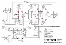
A note on this first, according to the circuit diagram, the resistors
R7 - R17 - R18 - R19 - R20
are not available on the circuit board at the factory according to the circuit diagram! )
R13 - 250 Ohm has wrong information, 370 Ohm is correct, as well as some capacitors C7-C8: 330uF and C12: 220uF can be seen with mixed values they are left soldered, but the circuit diagram has been corrected!
and others
Bewitch 6550/KT88 owner!
i am trying to write here with the help of google translate, hope understand me !!
I worked on the design of my Bewitch 6550 (bought in 2017 and had it come from China) a year ago or made changes externally.
(do you say facelift or?)
http://www.hifi-forum.de/index.php?action=browseT&forum_id=111&thread=4974&postID=728#728
So, get to work, there was a nice wooden plate made of mahogany and also some chrome dividers from the store shelving system that I was allowed to take with me, otherwise it would have ended up in the container.
And after almost two days of working on the wooden parts, the beautiful applications were finally attached to the device, on the front and the sides are glued, and on top the wooden top plate
(on the transformer cover) are glued with 2 embedded magnets.
The chrome tube protection at the front, even matching with wood, was optically very pleasing, I have to say it was worth the work on it, optically I like the device even better and it looks noble.
A few weeks ago the tube amplifier was open and finally modified internally, although only in crucial places where something really brings sound advantages.
All resistances are replaced by blue ones with 1%, several MKPs foils 0.68uF in addition to voltage capacitors and line filters, what was important for me was the change at the cinch input through better cabling and switching takes place directly at the inputs.
At the same time I took the circuit diagram created by Bewicht to hand and compared it with the circuit board, as some resistors and capacitors were not available or were soldered onto it with a different value.
After two days on the pc, I created a new circuit diagram with Paint, once the real thing on the (PCB) board, and with it
Identifies numerical components designation R11 - C1 and so on on the circuit board so that it is easier to find later.
I can pass on the changed circuit diagram and pictures to you here and would also be better to show here for other Bewitch owners.
A note on this first, according to the circuit diagram, the resistors
R7 - R17 - R18 - R19 - R20
are not available on the circuit board at the factory according to the circuit diagram! )
R13 - 250 Ohm has wrong information, 370 Ohm is correct, as well as some capacitors C7-C8: 330uF and C12: 220uF can be seen with mixed values they are left soldered, but the circuit diagram has been corrected!
SONDEKNZ.
( Agreed.
I only wish that amp manufacturers printed component naming (C3, R1, etc.) on the actual PCB!
Mapping the populated PCB - back to the schematic - is a bit like trying to unravel an Agatha Christie mystery.
Definitely not for the faint-hearted.
(Clearly reflecting my newbie status...) )
and here is my current PCB circuit schematic.
saltonm73
Attachments
-
 Bewitch 6550-KT88 Schaltung bestuckungzahlen4.jpg409.9 KB · Views: 146
 -
 IMG_20220106_135840.jpg396.2 KB · Views: 139
 -
 IMG_20220106_134245.jpg302.5 KB · Views: 120
 -
 IMG_20220106_134238.jpg220.3 KB · Views: 125
 -
 IMG_20220106_134255.jpg268.7 KB · Views: 113
 -
 IMG_20220106_135942.jpg377 KB · Views: 123
 -
 IMG_20220106_135912.jpg385.5 KB · Views: 133
@saltonm73
Nice job!
Looks like you have plenty of experience in these projects.
It has been a long time - too long - since I promised to report back about the improvements to our BEWITCH 6550 amp. This is because the amp - and all of our personal possessions - are still shipping from New Zealand to China, where we now live.
Whilst our modified amp did not really have a chance to full break-in after the changes, I can report that the sonic improvements were immediate and readily apparent - even to my wife, who does not consider herself an audiophile.
I would love to see a photo of your BEWITCH 6550 amp, complete with timber cheeks and trim, Saltonm73.
Also, I would like to hear your opinion on how your amp sounds, now that you have changed the circuit.
Best...
-SONDEKNZ
Kiwi, now living in China
what i did with my 6550 output stage was to use separate 470ohm 5 watt cathode resistors each with its own bypass caps....cathode currents of around 60ma and plate voltages of around 400vdc....i dislike trim pots and such......
SONDEKNZ.
( I would love to see a photo of your BEWITCH 6550 amp, complete with timber cheeks and trim, Saltonm73.
Also, I would like to hear your opinion on how your amp sounds, now that you have changed the circuit.
Best... )
as for sound!
I can only really judge when I have the amplifier from the work room on the second floor and the listening room (hobby room) in the basement.
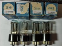
only yesterday after I took another picture of the inside, and again together with the cover, and selected the 6N8P tubes in pairs (2 old and 2 that I ordered a year ago) for testing ib everything is OK.
Unfortunately, about a year ago I ordered and received a new 6N8P as a quartet (from a well-known online shop that I don't want to mention)
When the package came, I only unpacked a few and looked to see if they were all due to transport.
only 2 weeks ago unpacked all 4 tubes and noticed that the tubes are different, inside and outside as they would come from 3 different productions, but only 2 are identical.
At the same time I ordered a new set of 4 that come directly from Russia, I have to be patient now, the delivery takes over 1 month.
( I would love to see a photo of your BEWITCH 6550 amp, complete with timber cheeks and trim, Saltonm73.
Also, I would like to hear your opinion on how your amp sounds, now that you have changed the circuit.
Best... )
as for sound!
I can only really judge when I have the amplifier from the work room on the second floor and the listening room (hobby room) in the basement.
only yesterday after I took another picture of the inside, and again together with the cover, and selected the 6N8P tubes in pairs (2 old and 2 that I ordered a year ago) for testing ib everything is OK.
Unfortunately, about a year ago I ordered and received a new 6N8P as a quartet (from a well-known online shop that I don't want to mention)
When the package came, I only unpacked a few and looked to see if they were all due to transport.
only 2 weeks ago unpacked all 4 tubes and noticed that the tubes are different, inside and outside as they would come from 3 different productions, but only 2 are identical.
At the same time I ordered a new set of 4 that come directly from Russia, I have to be patient now, the delivery takes over 1 month.
Attachments
- Home
- Amplifiers
- Tubes / Valves
- Bewitch KT88