Understood. So, would these values translate well for a Shared Cathode Resistor set-up - as I have described below?
SONDEKNZ,
Individual self bias resistors 2X Ohms
2 tube parallel shared self bias resistor X Ohms
4 tube parallel shared self bias resistor X/2 Ohms
Increase X Ohms to get less current
Reduce X Ohms to get more current
The Ratios of 2X for 1 tube, X for 2 tubes, X/2 for 4 tubes remains the same, regardless of the value of X.
Does that answer the question?
Last edited:

With lots and lots of negative feedback, until the amplifier is near clipping, the sound is nearly the same.
There are different levels of maximum power for different cathode resistors, so clipping is at different power levels, accordingly.
Just my opinion.
There are different levels of maximum power for different cathode resistors, so clipping is at different power levels, accordingly.
Just my opinion.
Individual self bias resistors 2X Ohms
2 tube parallel shared self bias resistor X Ohms
4 tube parallel shared self bias resistor X/2 Ohms
Increase X Ohms to get less current
Reduce X Ohms to get more current
The Ratios of 2X for 1 tube, X for 2 tubes, X/2 for 4 tubes remains the same, regardless of the value of X.
Thanks for this clarity, 6A3sUMMER.
Opinions seem to vary about exactly how much is a safe minimum, but it is evident that (the current) 375-Ohms resistance shared between two 6550 tubes working in triode, may not be enough to be safe.
So, the above statement is untrue.
It seems like 375-Ohm value in a Shared Cathode Resistor position serving two 6550 tubes is fine, after all.
Correct?
Last edited:
the choice of individual cathode resistors depends on how much tube dissipation you can be comfortable with....higher plate voltage will need higher cathode resistor values and vice versa...
as always, tube dissipation is key...if your tube has a maximum plate rating of say 30 watts, then 80% of that is 24 watts, so try to stay inside of this limit...
as always, tube dissipation is key...if your tube has a maximum plate rating of say 30 watts, then 80% of that is 24 watts, so try to stay inside of this limit...
Most SOUND IMPACTING Resistor positions?
Through this learning journey, I have read a lot of discussions around whether or not different types of resistors sound different. I appreciate there are wildly disparate opinions.
My experiments below - with this BEWITCH 6550 amp and in our system - easily revealed to both my wife and I, significant difference between CARBON FILM and METAL FILM resistors in the GNFB position - R14 - given same values, wattage, etc.
On this basis, I am keep to experiment and learn more, so I wanted to ask for opinions from those with more experience.
QUESTION: Which resistor positions are seen as most impacting on sound quality?
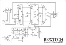
I have provided the original schematic for reference to this circuit, bearing in mind that some of the factory-fitted resistor are materially different, from those on the schematic. This amp is so quiet and well-behaved, that for any changes, I intend to stick with the current factory-fitted resistor values - and simply try different types of resistors.
I am thinking that R15/R16, R11/R12 and R9/R10 are the critical SOUND IMPACTING positions, but very happy to be corrected here.
Recommendations invited.
Through this learning journey, I have read a lot of discussions around whether or not different types of resistors sound different. I appreciate there are wildly disparate opinions.
My experiments below - with this BEWITCH 6550 amp and in our system - easily revealed to both my wife and I, significant difference between CARBON FILM and METAL FILM resistors in the GNFB position - R14 - given same values, wattage, etc.
On this basis, I am keep to experiment and learn more, so I wanted to ask for opinions from those with more experience.
QUESTION: Which resistor positions are seen as most impacting on sound quality?
I have provided the original schematic for reference to this circuit, bearing in mind that some of the factory-fitted resistor are materially different, from those on the schematic. This amp is so quiet and well-behaved, that for any changes, I intend to stick with the current factory-fitted resistor values - and simply try different types of resistors.
I am thinking that R15/R16, R11/R12 and R9/R10 are the critical SOUND IMPACTING positions, but very happy to be corrected here.
Recommendations invited.
Attachments
Last edited:
you can play around with the open loop gains, tube dissipations and stuff to give you a different flavor......
@TonyTecson
Many thanks for your thoughts on this Tony. Great support!
If you could only change a couple of these resistors, where would you start?
Many thanks for your thoughts on this Tony. Great support!
If you could only change a couple of these resistors, where would you start?
Last edited:
@TonyTecson
Sorry. I've missed the relevance of your comment, to my question... 😕
i get good results if the input tube is 6H8 and the phase splitter is a 6H9...
Sorry. I've missed the relevance of your comment, to my question... 😕
changing operating points with the swapping of tubes is one way without changing anything on the circuit itself, plus it is very easy to go back if you find the results not to you liking...
another way, is to put a 220k 3 watt resistor from the plate of the 6550 to the plate of the driver tube introduced local feedback and you can see if not having the overall feedback connected is to your liking....
this will work best when the switch at the output is on triode mode...
these are just baby steps that you can do...
My 2 cents about the modifications:
- Still the worst thing is the fixed bias using a Electrolyte Cap. The issue here is the absorption voltage given from the Electrolyte Cap. The get ride requires a negative voltage. I did this on my SLM-100 and the sound was more clear, no more echo's...
Removing Plastic covers from Capacitors - diyAudio
@HpW
Are you suggesting bypassing the Shared Cathode Resistor(s) with non EL caps instead?
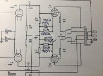
It's labelled R13 and it's in parallel with C5. This is the "shared" cathode resistor.
Ohm's law says we need to double the resistance to get the same voltage drop with half the current, so make R13 250R into two 500R resistors, each with their own cap, one set for each output tube. In a stereo push pull amp, that's 4 sets.
@kodabmx
Many thanks for this very helpful suggestion.
I have read through this entire thread many times and drawn some conclusions on how this Shared Cathode Resistor arrangement can be split into Individual Cathode Resistors.
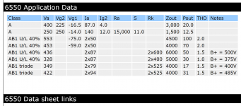
Below I have shared the 6550 tube datasheet, relating to "triode" operation, which is our preferred sound on the BEWITCH amp.
I have also attached my schematic workings on how I understand this upgrade should look like.
I'm hoping you and/or others might be kind enough to check my workings, before I progress further. Appreciated.
Attachments
you can get rid of that triode ultra linear switch and fix that to triode, so one less to worry about..
measure the cathode voltage on the 600ohm bias resistors, to get 60ma cathode current, you should be able to measure 36volts more or less....if your tubes are perfectly matched, you should be able to get equal readings..
measure the cathode voltage on the 600ohm bias resistors, to get 60ma cathode current, you should be able to measure 36volts more or less....if your tubes are perfectly matched, you should be able to get equal readings..
SONDEKNZ,
I like your latest schematic, that shows the use of Individual Self Bias R and bypass C networks on the output tubes.
The input stage provides relatively balanced DC voltages to the phase splitter.
(schematic in Post # 109).
But the parallel 20k resistors in the splitter cathodes is a less than ideal current sink (10k).
That means the amplitude of the 2 phases is not equal (creates 2nd Harmonic Distortion at the amplifier speaker output terminals).
The Global Negative Feedback reduces that 2nd Harmonic Distortion (but that means it has that distortion to correct).
Measure the DC voltage across the parallel 20k resistors.
Depending on that voltage, there may be quite a few Constant Current Sinks that have a very low burden voltage (minimum voltage where they still are a Constant Current Sink).
Using one of those CCS instead of the two 20k resistors, will eliminate the 2nd harmonic distortion of the phase splitter. Then the Global Negative Feedback will not have to take care of it (on less job for the feedback to do).
Well, there is another possibility, the input stage is not AC balanced. The signal only comes from one plate. And that tube has 2nd Harmonic Distortion, which is not cancelled by the other input tube.
Perhaps the amp was designed for the first stage 2nd HD to cancel the phase splitter 2nd HD.
The way to find that out is to Triode wire the output tubes, and open the Global Negative Feedback loop (disconnect R14 from the output transformer secondary).
Then measure the 2nd Harmonic Distortion. If it is very low, then probably there is some 2nd HD cancellation by the opposite action of the input tube and phase splitter tube.
If the 2nd Harmonic distortion is high with the Global Negative Feedback removed, you may want to try a low burden voltage CCS in the cathodes of the phase splitter.
Last edited:
you can get rid of that triode ultra linear switch and fix that to triode, so one less to worry about..
measure the cathode voltage on the 600ohm bias resistors, to get 60ma cathode current, you should be able to measure 36volts more or less....if your tubes are perfectly matched, you should be able to get equal readings..
Thanks TonyTecson.
Good thoughts about removing the TRIODE/UL switch to leave the amp hard-wired in (our preferred) TRIODE operation.
Another benefit is that I can get rid of the delicate switches and switch wiring that need to be removed each time I lift the PCB.
If I hard-wire for triode operation, I would conceivably reduce the proposed 600-Ohm 6550 Individual Cathode Resistors down to 525-Ohms, as per the 6550 Datasheet recommendations for triode operation.
Perhaps even 500-Ohms - as the current Cathode Bias is approximately 375-Ohms; a half-share of the original shared 750-Ohms. I am keen to keep the sound the same, if possible.
Does this make sense?
Giving it some thought...
SONDEKNZ,
I like your latest schematic, that shows the use of Individual Self Bias R and bypass C networks on the output tubes.
The input stage provides relatively balanced DC voltages to the phase splitter.
(schematic in Post # 109).
But the parallel 20k resistors in the splitter cathodes is a less than ideal current sink (10k).
That means the amplitude of the 2 phases is not equal (creates 2nd Harmonic Distortion at the amplifier speaker output terminals).
The Global Negative Feedback reduces that 2nd Harmonic Distortion (but that means it has that distortion to correct).
Thanks for this support 6A3sUMMER.
I have been working my way over the amp PCB, making best efforts to determine which resistors on the PCB equate to which positions in the schematic. A type of mapping exercise.
Frankly, this is very challenging, as it appears that many of the values shown on the schematic, bear very little resemblance to what is actually on the PCB.
For example, it appears that the two paralleled 20K resistors, have been replaced with individual 10K resistors. [I need to confirm how the schematic has changed in this regard - and if the two 6N8P tubes are still connected - but there are no 20K resistors anywhere in the amp; and two 10K resistors that were not mentioned at all on the schematic...]
I'm aware that the helpful members on this forum can only provide assistance based upon the accuracy and depth of information that I share.
Therefore, I believe that need to complete this mapping exercise and provide an "actual" schematic - for further discussion to be worthwhile.
This might take a while. I'm on it.
Thanks to both you and TonyTecson for hanging with me, on this project.
Last edited:
- Home
- Amplifiers
- Tubes / Valves
- Bewitch KT88