A special note about the Bewitch, I don't know whether you have already noticed it or known, you have also taken a look at your device and compared the wiring diagram!
Actually, the two channel sides on the right as on the left should be the same as with other known tube amplifiers, or should be switched identically,
Strangely enough, the Bewitch has the left channel side
namely additionally supplied with voltage only by a tap, I also have this on the circuit diagram with an A
Letter
countersigned, from the transformer output of the two 6.3v 2A go over 2x 100 ohm resistors merged again and
Power supplies the two 6550
Cathode (input 8).
On the right side of the channel this circuit is not available, I was surprised, but it was developed by the manufacturer, I don't know why and why!
SONDEKNZ
https://www.diyaudio.com/community/...al-cathode-bias-upgrade-schematic-jpg.929008/If it is now divided in the middle into two sides, as suggested or also marked in your circuit diagram, it does not do much in principle, due to the additional voltage on the cathode you put them back together, then it can stay as it is or !?
Hello Tony Tecson.
( what i did with my 6550 output stage was to use separate 470ohm 5 watt cathode resistors each with its own bypass caps....cathode currents of around 60ma and plate voltages of around 400vdc....i dislike trim pots and such......)
How would you do it at this point, if there as I have just pointed out and written above?
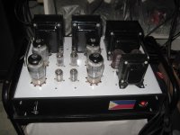
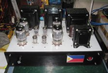
this is how did my 6550 pp amp... the cathode bypass resistors are visible at both ends of the build..Hello Tony Tecson.
( what i did with my 6550 output stage was to use separate 470ohm 5 watt cathode resistors each with its own bypass caps....cathode currents of around 60ma and plate voltages of around 400vdc....i dislike trim pots and such......)
How would you do it at this point, if there as I have just pointed out and written above?
Attachments
Tony Tecson.
(this is how did my 6550 pp amp... the cathode bypass resistors are visible at both ends of the build..)
to clarify again
Strangely enough we have here on the left channel of the two 6550 cathodes as you can see
are additionally supplied with voltage from the transformer, I also have this on the circuit diagram with an A
letter countersigned,
from the transformer output of the two 6.3v 2A go through 2x 100 ohm resistors that are put back together and the
Voltage only supplies the two 6550
Cathodes (input 8) of the left channel side,
you can't separate there either, as suggested, you would first have to cut the supply from the transformer on the left side then it should work.
This circuit is not available on the right side of the channel, I will show you what I mean by means of the picture. !!
why that
planned by the Bewitch technicians
I don't know if anyone has an answer. !
for this reason
here again, the circuits are different can't be compared with yours, your tube amplifier is wired freely without a circuit board, certainly has a different circuit diagram than the Bewitch 6550/KT88.
Tony Tecson
is there a circuit diagram of your amplifier to compare !!
Attachments
your schematics show three 6.3 filament windings, in the power traffo, the one with the 100 ohm resistors are probably used for dc ground lifting, though not clearly shown in schematics, so there are two other filament windings that is used for the output tubes filaments...Tony Tecson.
(this is how did my 6550 pp amp... the cathode bypass resistors are visible at both ends of the build..)
to clarify again
Strangely enough we have here on the left channel of the two 6550 cathodes as you can see
are additionally supplied with voltage from the transformer, I also have this on the circuit diagram with an A
letter countersigned,
from the transformer output of the two 6.3v 2A go through 2x 100 ohm resistors that are put back together and the
Voltage only supplies the two 6550
Cathodes (input 8) of the left channel side,
you can't separate there either, as suggested, you would first have to cut the supply from the transformer on the left side then it should work.
This circuit is not available on the right side of the channel, I will show you what I mean by means of the picture. !!
why that
planned by the Bewitch technicians
I don't know if anyone has an answer. !
for this reason
here again, the circuits are different can't be compared with yours, your tube amplifier is wired freely without a circuit board, certainly has a different circuit diagram than the Bewitch 6550/KT88.
Tony Tecson
is there a circuit diagram of your amplifier to compare !!
my amp used the ef86 input voltage tube and 6cg7 long tail phase splitters...
sorry, i did not draw any schematics for my amp....but it was inspired by the Mullard 5-20,
only, i used G2 regulated psu at lower voltage, of around 300vdc, and the separate cathode resistors of 470 ohm 5 watt resistors.....
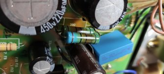
In the tube amplifier, the old ceramic resistors had 2x 750 ohms 5% (R13) against the new blue 1% before each 5 watts and new ones are also 5 watts, but after a test phase of 10 hours they no longer see blue, they get too hot look ?
The question now is whether I leave them in or solder the old ceramic resistors on again!
Sure, the ceramic resistors have better heat dissipation.
Of course I have often seen in other devices with many power supplies that the resistors get very hot and were darker, and over the years nothing has caused damage as a result, but I want to be sure that nothing bad happens there
high currents flow!
I looked online for 10 watt resistors but you can't get them here in this country!
what do you all mean ?
Attachments
I measured the resistances, the value it should be has remained, has not changed.
So I don't need to worry too much!
I think it's normal for the surface color to change when it's hot.
thank you
So I don't need to worry too much!
I think it's normal for the surface color to change when it's hot.
thank you
saltonm73,
Such a long thread, that means I do not know what your schematic and topology is like.
6550 tubes are often known to have thermal run-away. Some new 6550 tubes can not live up to the old 6550 specifications.
What is the g1 DC resistance to ground (check against the maximum g1 resistor data sheet specs, self bias is one spec, fixed adjustable bias is a lower resistance spec)?
What is the g2 voltage?
What is the plate voltage?
What is the cathode current?
Is g2 in Beam Power mode, or in Ultra linear mode?
As a general rule, Beam Power mode is harder on a tube than Ultra Linear mode, if the quiescent screen voltage is the same (but Beam Power mode does not always regulate the screen voltage, and UL screen voltage is higher than plate voltage because of the additional voltage drop from the screen tap to the plate tap).
I normally use resistors that are rated at 5 times the power they will be required to dissipate. And putting them side by side actually reduces their power rating (they heat each other, no free air between them).
Your coupling caps to the 6550 g1 grid, are they leaky (can not use an ohmmeter to test that, instead measure the voltage at g1 grid (takes more care and figuring if you are using fixed adjustable bias; is simple if you are using self bias because the grid leak resistor returns to ground/zero Volts)?
in either case, the grid should either be exactly at the fixed adjustable voltage, or at zero volts, respectively. Any voltage across the g1 return resistor indicates grid current; anything more than 20mV may indicate a problem (test when the amp is warmed up for a few minutes).
What is the quiescent plate dissipation?
What is the quiescent screen dissipation?
Using both the plate and the screen at or near maximum dissipation, will require a g1 DC return resistance that is lower than the specified data sheet value.
Is your amplifier subjected to Hot Starts?
A hot start is when the power goes out momentarily, and then comes back on when the filaments are still warm (power mains quick drop-out and return; or you turning the warmed up amp off, and then quickly back on.
Have you tried using KT88 instead of 6550?
470 Ohms and 60mA is 28.2V bias.
(28.2V)squared / 475 Ohms = 1.69 Watts.
Parallel 750 Ohms . . . 750 Ohms/2 = 375 Ohms; 28.2V/375 Ohms = 75.2 mA.
I am not sure what you are using or doing here.
Sorry for the many questions.
Not all things that are engineered are correctly engineered . . .
Remember the Tacoma Narrows Bridge.
Google it and see the YouTube video (can not copy the YouTube link).
Last edited:
hello 6A3sUMMER,
I couldn't answer your many questions sooner, had to wait for the new Mcaps shipment first to wear everything I had planned on the device at once.
So, the 4 MCaps 0.47u are exchanged for better Jantzen Superior Z-Cap and also
solder another 0.68u at another point.
to your questions about the tubes!
( *Some new 6550 tubes may not meet old 6550 specs *)
Doesn't that mean the Russian 6550 EH?
(* Have you tried using KT88 instead of 6550?*)
For the KT88 I'm not interested in changing it at the moment, maybe I'll try a set of 4 matched tubes at some point!
Regarding your other questions about the datasheet specs,
the measurements could only be carried out a few days ago,
Triodes or Ultra Linear mode?
I think it stays with the UL mode!
Question about R13?
(I typically use resistors rated at 5x the power they need to dissipate. And putting them side by side actually reduces their power rating (they're each other, no free air between them).)
I gave the double resistors R13 more air to each other (5mm), and the
Observed temperature over a few hours in operation, so there can be no impairment compared to the ceramic version.
(Is your amp subject to hot starts?)
no, after switching on, the device is on for a few hours!
(* 470 ohms and 60mA is 28.2V bias.
(28.2V) squared / 475 ohms = 1.69 watts.
Parallel 750 ohms. . . 750 ohms / 2 = 375 ohms; 28.2V / 375 ohms = 75.2mA.
I'm not sure what you are using or doing here.*)
I think there have been some reading and circuits with what I could find on the net before I posted here, the measurements I made are also almost identical to the other circuit diagrams from another link such as (Lampizator) or others.
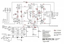
look at my new current circuit diagram with measurements with volt values, there are many places where I measured.
I couldn't answer your many questions sooner, had to wait for the new Mcaps shipment first to wear everything I had planned on the device at once.
So, the 4 MCaps 0.47u are exchanged for better Jantzen Superior Z-Cap and also
solder another 0.68u at another point.
to your questions about the tubes!
( *Some new 6550 tubes may not meet old 6550 specs *)
Doesn't that mean the Russian 6550 EH?
(* Have you tried using KT88 instead of 6550?*)
For the KT88 I'm not interested in changing it at the moment, maybe I'll try a set of 4 matched tubes at some point!
Regarding your other questions about the datasheet specs,
the measurements could only be carried out a few days ago,
Triodes or Ultra Linear mode?
I think it stays with the UL mode!
Question about R13?
(I typically use resistors rated at 5x the power they need to dissipate. And putting them side by side actually reduces their power rating (they're each other, no free air between them).)
I gave the double resistors R13 more air to each other (5mm), and the
Observed temperature over a few hours in operation, so there can be no impairment compared to the ceramic version.
(Is your amp subject to hot starts?)
no, after switching on, the device is on for a few hours!
(* 470 ohms and 60mA is 28.2V bias.
(28.2V) squared / 475 ohms = 1.69 watts.
Parallel 750 ohms. . . 750 ohms / 2 = 375 ohms; 28.2V / 375 ohms = 75.2mA.
I'm not sure what you are using or doing here.*)
I think there have been some reading and circuits with what I could find on the net before I posted here, the measurements I made are also almost identical to the other circuit diagrams from another link such as (Lampizator) or others.
look at my new current circuit diagram with measurements with volt values, there are many places where I measured.
Attachments
1. Turn an amplifier on, and leave it on for 30 minutes, or on all day long.
Then . . .
Your Power Company has a power glitch, the power goes out for perhaps 5 seconds or perhaps 15 seconds.
(The 6550 cathodes are still hot and glowing).
Then, the power comes on again after the 5 or 15 seconds.
That is called a Hot Start. (sometimes that takes out fuses, output tubes, etc.) depends on the amplifier circuit and parts.
2. You are using common cathode bias for the 6550 tubes. And the g1 resistors to ground are 220k Ohms.
The maximum g1 resistance to ground for 6550 with cathode bias is 250k, you are close there (a wimpy tube may have/get thermal run away current).
Unless the 6550 tubes are very well matched, the plate currents may not be equal.
(especially since the cathodes do not have their own individual self bias resistors and individual bypass caps).
You already have two 750 Ohm self bias resistors in parallel and one bypass cap; it is easy to use one 750 Ohm per cathode, and then add one bypass cap).
Push pull transformers want equal plate currents, or else the laminations will saturate too early.
3. Do not switch from UL mode to Triode mode, or Triode to UL when the amplifier is powered.
Wait until the amplifier is powered down, and cooled off, then change the switch position before power-up.
Last edited:
(especially since the cathodes do not have their own individual self bias resistors and individual bypass caps).
You already have two 750 Ohm self bias resistors in parallel and one bypass cap; it is easy to use one 750 Ohm per cathode, and then add one bypass cap)
I already know that and I understand your argument,
per cathode (K8) each with a 750-ohm and a bypass capacitor would do the same, but...
again to clarify, because apparently still no one has paid attention to it!
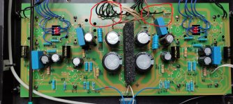
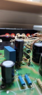
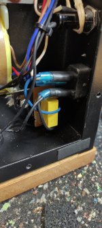
The Bewitch KT88/6550 only have, again only on the left channel side (the right side is not supplied with it), the cathodes (K8) are additionally supplied with 6.3v voltage, which I also marked with A on the circuit diagram, and also with circle above in attached picture to clarify where it is.
I can't simply remove or remove this voltage of 6.3v, which changes the bias, doesn't it?
Oh, now I see the connection from one end of the filament winding to one pin 8 of one 6550.
That means all the tubes on that filament winding are raised to 42VDC, the common bias voltage of two 6550 tubes of one channel.
There is no reason that you can not use two individual cathode self bias resistors on that one channel, and two bypass caps, one for each of the self bias resistors. Each cathode will have a bias resistor of 2X the resistance of what was the common bias resistor resistance.
Plate currents should be fairly well matched doing that, unless the two tubes are quite poorly matched.
But, you can not connect the virtual tap of the 100 Ohm resistors to point A, and also connect one end of the filament winding to the cathode. That is sort of OK, but simply shorts one of the 100 Ohm resistors, which cancels the purpose of a virtual center tap.
Either connect one end of the filament winding to the cathode, or do not do that, and instead connect the virtual center of the two 100 Ohm resistors to the cathode.
And, one end of a 6.3V filament winding that is tied to one cathode does not change the self bias voltage of that cathode.
The bias voltage is not changed, whether you use a common self bias resistor, or individual self bias resistors.
Last edited:
I already know that and I understand your argument,
per cathode (K8) each with a 750-ohm and a bypass capacitor would do the same, but...
again to clarify, because apparently still no one has paid attention to it!
The Bewitch KT88/6550 only have, again only on the left channel side (the right side is not supplied with it), the cathodes (K8) are additionally supplied with 6.3v voltage, which I also marked with A on the circuit diagram, and also with circle above in attached picture to clarify where it is.
I can't simply remove or remove this voltage of 6.3v, which changes the bias, doesn't it?
if you want to go individual cathode resistor biasing, you will have to free pins 1+8, and install the individual 470 ohms 5 watt cathode resistor bias and bypass caps, this should not be so hard to do in your amp...
TonyTecson,
If the correct parallel cathodes' combined self bias resistor (as listed on the schematic) is two 750 Ohm resistors in parallel (375 Ohms, parallel), then . . .
The correct individual self bias resistors for each individual cathode is 750 Ohms.
That will give the same self bias volts.
Where did the 470 Ohms resistance come from, I missed that.
Thanks!
EL34 and 6CA7 tubes need pin # 1 to be connected to pin # 8.
6550 and KT88 tube's pin # 1 do not have any internal connection to the tube, but some of those tubes connect the outside metal shield to pin # 1.
Caution: If the cathode is self biased, and you connect pin # 1 to pin # 8, on some of 6550 / KT88 tubes, the outside metal shield will be at an elevated voltage.
Tube Rolling, even with 6550 and KT88 . . .
Plug and Play . . . becomes Plug and Pray (that nothing goes wrong).
Last edited:
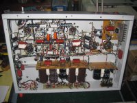
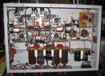
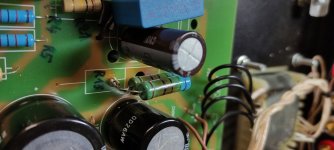
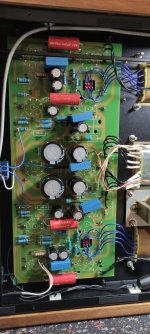
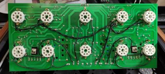
Should be of interest to others in this thread, so I'm including a picture of the PCB from below so you can see the electrical connections better.
and those who are familiar with it can certainly judge better and also provide correct information on the subject.
I leave my Bewitch 6550 as they are for the time being in the modified version
and listen for a while, sounds very good to my ears and I'm satisfied.
and those who are familiar with it can certainly judge better and also provide correct information on the subject.
I leave my Bewitch 6550 as they are for the time being in the modified version
and listen for a while, sounds very good to my ears and I'm satisfied.
Attachments
40 years working in electronics maintenance, installation, repair, calibration, design engineering, marketing, and technical support, I had to work with a lot of PCBs.
I even had to work with Surface Mount Technology (SMT), with super fine spaced IC leads, salt and pepper parts, etc.
Thank God all my tube amplifiers are point to point wiring.
They do not have any PCBs.
Just my preference.
I even had to work with Surface Mount Technology (SMT), with super fine spaced IC leads, salt and pepper parts, etc.
Thank God all my tube amplifiers are point to point wiring.
They do not have any PCBs.
Just my preference.
Last edited:
TonyTecson,
If the correct parallel cathodes' combined self bias resistor (as listed on the schematic) is two 750 Ohm resistors in parallel (375 Ohms, parallel), then . . .
The correct individual self bias resistors for each individual cathode is 750 Ohms.
That will give the same self bias volts.
Where did the 470 Ohms resistance come from, I missed that.
Thanks!
EL34 and 6CA7 tubes need pin # 1 to be connected to pin # 8.
6550 and KT88 tube's pin # 1 do not have any internal connection to the tube, but some of those tubes connect the outside metal shield to pin # 1.
Caution: If the cathode is self biased, and you connect pin # 1 to pin # 8, on some of 6550 / KT88 tubes, the outside metal shield will be at an elevated voltage.
Tube Rolling, even with 6550 and KT88 . . .
Plug and Play . . . becomes Plug and Pray (that nothing goes wrong).
sorry if i confused you, that 470 ohm cathode resistor is based on a plate of around 400 volts and a G2 of around 350v, i run my 6550 in pentode mode supplied G2 with mosfets regulated supply...the dissipation is around 24 watts...
the amp runs flawlessly till today....
re: pin1 connection to tube metal base is easy to confirm with a dmm on a continuity mode.....i bet this is not an issue unless yours is an all metal envelope wherein the metal envelope is always connected to pin 1 in and octal tube....
reason i recommend connecting pins 1 & 8 is to allow you to use the EL34 should you wish...
Attachments
Last edited:
@saltonm73
I spotted your similar post over at the Italian T-forum - which prompted me to head-on over to diyAudio... and here you are!
It seems you and I have travelled a similar path with the BEWITCH 6550, however, I have opted to hard-wire the amp for TRIODE operation.
Nice work on your BEWITCH!
Regarding (R13) the (original) shared cathode bias for the 4 x 6550, I opted to install paralleled pairs of MILLS 750K/12W non-magnetic, low-inductance wirewound resistors, per pair of 6550. This provides 375K of cathode resistance per pair. Worth noting that this change alone dramatically improved the sound, over the factory sandcast resistors.
I recently had another very nice sonic gain by installing a quality polypropylene 2.2uF 250W capacitor across each C5. This has brought a little more sparkle to the sound, without adding any brightness.
I wanted to ask you a couple of questions about your modifications - bearing in mind that by comparison, my BEWITCH still runs the 6SL7 in the first preamp tube position - and it only operated in TRIODE:
Why did you add a .68uF capacitor between C3/4 and C5? Can you report any impact on the sound?
What did you add a 1Meg resistor across the volume potentiometer?
Lastly, why did you run the 6SN7 in the first tube position - instead of the 6SL7? I fear that this will mess with the amplifier Gain and NFB structure.
I look forward to your thoughts. Appreciated.
40 years working in electronics maintenance, installation, repair, calibration, design engineering, marketing, and technical support, I had to work with a lot of PCBs.
I even had to work with Surface Mount Technology (SMT), with super fine spaced IC leads, salt and pepper parts, etc.
Thank God all my tube amplifiers are point to point wiring.
They do not have any PCBs.
Just my preference.
Fair enough!
As a learner, I feel the exact opposite.
Our beloved BEWITCH 6550 - with its PCB lay-out and label puzzles - at least gives me a sporting chance of (one day) understanding the circuit schematic.
Our wonderful LEBEN CS300F - with its point-to-point "artisan" construction - leaves me in a complete muddle. No chance to work on that little gem.
Do you prefer point-to-point wiring because you feel it sounds better? Or is it just because you can find your way around the circuit easier? Or perhaps both?
So, the question begs: Why do the hard-core audio guys all prefer point-to-point wiring?
- Home
- Amplifiers
- Tubes / Valves
- Bewitch KT88