BEWITCH 6550 UPDATE... Converted back to original circuit
It's been a while since I posted an update on our BEWITCH 6550 integrated amp.
As a recap, the previous owner - a qualified EE - [prompted by a few posts by the LAMPIZATOR main man Lukasz Fikus] changed the amp circuit by: -
1. Bypassing C3 and C4 .47uF capacitors with 2.2uFuf capacitors
2. Bypassing R1 (and its counterpart - not sure what it is named) with a 100uF cap
3. Swapping preamp tube positions. Essentially both V1a and V1b swapped with V2a and V2b.
The previous owner felt that this allowed the amp to provide greater top-end extension.
To our ears though, something didn't sound quite right, almost as if there was some kind of restraint to the sound. An imbalance. So, I recently removed the additional caps and moved the preamp tubes back to their original positions.
As a result, the amp now sounds very good - and much more balanced - but perhaps with a little less detail than the previous configuration.
So I am now seeking ways to improve the sound of the original circuit.
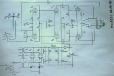
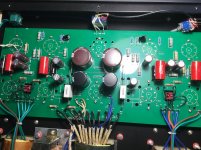
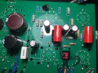
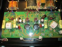
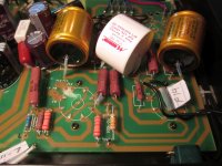
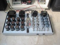
Shown again below is the original circuit - and also some photos of the amp interior BEFORE I converted it back to the original circuit.
Where worthwhile, it is now my hope to be able to upgrade some of the cheaper components to achieve improved sonics.
As a newbie, one of the challenges in unravelling this circuit, is trying to understand exactly which components are in the signal path - and/or impact sound quality - and which do not.
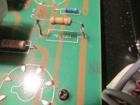
EXAMPLE: I notice that each side of the amp circuit has two 750-Ohm/5W sandcast resistors paralleled to deliver the required 390-Ohm resistance.
Sandcast resistors get a bit of a bad rap sound-wise, so I thought this might be a good component to upgrade - to Mills non-ferrous - to test this theory.
Trouble is, on the schematic, there is simply no mention of 390-Ohm resistor anywhere.
What have I missed here?
It's been a while since I posted an update on our BEWITCH 6550 integrated amp.
As a recap, the previous owner - a qualified EE - [prompted by a few posts by the LAMPIZATOR main man Lukasz Fikus] changed the amp circuit by: -
1. Bypassing C3 and C4 .47uF capacitors with 2.2uFuf capacitors
2. Bypassing R1 (and its counterpart - not sure what it is named) with a 100uF cap
3. Swapping preamp tube positions. Essentially both V1a and V1b swapped with V2a and V2b.
The previous owner felt that this allowed the amp to provide greater top-end extension.
To our ears though, something didn't sound quite right, almost as if there was some kind of restraint to the sound. An imbalance. So, I recently removed the additional caps and moved the preamp tubes back to their original positions.
As a result, the amp now sounds very good - and much more balanced - but perhaps with a little less detail than the previous configuration.
So I am now seeking ways to improve the sound of the original circuit.
Shown again below is the original circuit - and also some photos of the amp interior BEFORE I converted it back to the original circuit.
Where worthwhile, it is now my hope to be able to upgrade some of the cheaper components to achieve improved sonics.
As a newbie, one of the challenges in unravelling this circuit, is trying to understand exactly which components are in the signal path - and/or impact sound quality - and which do not.
EXAMPLE: I notice that each side of the amp circuit has two 750-Ohm/5W sandcast resistors paralleled to deliver the required 390-Ohm resistance.
Sandcast resistors get a bit of a bad rap sound-wise, so I thought this might be a good component to upgrade - to Mills non-ferrous - to test this theory.
Trouble is, on the schematic, there is simply no mention of 390-Ohm resistor anywhere.
What have I missed here?
Attachments
Well the first mistake was doing "upgrades" from Lampizator.
Adding 2.2ufd to those coupling caps is a recipe for blocking distortion, and completely unnecessary. With stock caps, low frequency response is 1.5Hz (approx), with the 2.2ufd is about .33Hz. Adding nothing but more subsonic noise.
Putting a 6N9P tube in the second position will kill drive to the 6550 tubes. It just isn't capable of supplying the drive.
Bypassing R1 is useless and senseless and may affect the balance of the phase splitter as well.
Those two 750 ohm resistors give 375 ohms, not 390, and they are the cathode resistors for the output tubes. That may or may not be correct depending on the plate voltage. You'd have to measure the voltage across that, divide by two and divide by the resistance to get the current through each output tube to see if it is correct.
@audiopro
Hi Dan, Many thanks for endorsing my returning this amp circuit to its original design - and thanks for explaining why the former owner's "upgrades" sounded wrong.
To be fair to Lukasz Fikus of LAMPIZATOR, the former owner did NOT follow Lucasz' upgrade recipe; and instead, just did his own thing. I have no idea if the exact Lukasz Fikus upgrades would have delivered a better result than the former owner achieved. This will have to remain an unknown.
The cathode resistors for the output tube mentioned below - that are currently paralleled to deliver 375-Ohms of resistance - are sitting in a position that is clearly labeled "390". I assume the manufacturer decided 375-Ohms is close enough.
The mystery to me, is why this 390-Ohm (375) resistor is not visible anywhere on the schematic. Perhaps I have missed it somewhere?
Last edited:
SONDEKNZ,
Your schematic in Post # 61 shows the 6550 g1 grids are returned to 220k Ohms.
The maximum g1 spec for Self Bias is 250k.
That is within the specs, but may be cutting it close, because . . .
It uses a Common self bias resistor. One tube may choose to hog the current.
You have to use very well matched 6550 or the output transformer will saturate early.
Use Robust 6550 and get away with 220k
Use Less Robust 6550 and get thermal run-away (Bust).
If you do enough tube rolling, you may roll one of them all the way to the garbage can.
Your Mileage May Vary.
Last edited:
@6A3sUMMER
Thanks for this warning. We will not be looking to do tube rolling, other than replacing tubes when required.
Nevertheless I would like to reduce this risk, as the risk increases as tubes age - correct?
Can you see any quick-win resolutions to this risk? Perhaps varying the value of particular components to bring down the margin of risk?
Appreciated.
Replace the 250 Ohm self bias resistor.
Use an individual 500 Ohm self bias resistor for each 6550.
Use an individual bypass cap across each individual self bias resistor.
Measure the voltage across all the 500 Ohm resistors.
Volts/500 = the cathode current of a single 6550.
I prefer to keep my output tubes to have 1mA or less of un-balanced current in the output transformer primary (for example, a 40.5 mA and a 39.5mA = 1mA un-balance).
You can check for this with the tubes you have. You might find of the 4 tubes you have, they might match better if you swap one from Left to Right channel, and one from Right channel to Left channel.
Example:
40 and 42 in Left channel, 39 and 41 in Right channel. Move so 39 and 40 are in the Left channel, and 41 and 42 are in the right channel.
You can check the current as the tubes age 1 week, 2 weeks, then 6 months, 1 year, 2 year, etc.
Often at first, infrequent when you see that they are aging together.
Done.
Happy Listening!
Last edited:

Replace the 250 Ohm self bias resistor.
Use an individual 500 Ohm self bias resistor for each 6550.
Use an individual bypass cap across each individual self bias resistor.
@2A3sUMMER
Many thanks for this info. Seems simple enough.
Do you have any suggestions on the value/power handling of the bypass cap for these new, individual self bias resistors?
Presumably these new self-bias resistors - and associated bypass caps - will connect between each individual 6550 and ground.
Last edited:
Replace the 250 Ohm self bias resistor.
Use an individual 500 Ohm self bias resistor for each 6550.
Use an individual bypass cap across each individual self bias resistor.
good thing, this is how i do my pp amps....6j32/ef86, 6cg7 ltp splitter and 6550 finals..
Attachments
That's the 250 ohm marked on the schematic. Design change probably.The mystery to me, is why this 390-Ohm (375) resistor is not visible anywhere on the schematic. Perhaps I have missed it somewhere?
@audiopro
Thanks for this Dan.
Okay - so this is the 6550 Cathode Bias resistor, currently labeled R13 on the supplied schematic. Mystery solved!
This 390-Ohms resistor (375 actual) that is currently in place is a considerable increase over the labeled R13 at 250-Ohms.
As discussed earlier in this thread, I guess the designer realized they were cutting this way too fine with 250-Ohms and subsequently fitted 390-Ohms in the R13 position.
In some ways, it still does not seem high enough resistance.
Meanwhile, I have been reading more by respected tube amp designer - Roger Modjesky - about why he believes cathode bias (self bias/auto bias) amps always:
A: sound less good than fixed bias (variable pot for each tube) amps; and
B: squander valuable (usable) output power
This is a very big subject...
That's the 250 ohm marked on the schematic. Design change probably.
happens all the time, that is because the builder was aiming for a particular cathode current in his amp...
and the reason for this is that the psu that the actual build had gave different result, the schematic only shows you haw to build a particular amp, but things do change as you get more experience...
A: sound less good than fixed bias (variable pot for each tube) amps; and
B: squander valuable (usable) output power
these are iffy's, our listening tests did not reveal significant loss of power, instead the amp lasted a long time without so much maintenance...
power? what watts? the power in our amps are designed and measured using sine waves, but who listens to sine waves? not me.....😀
and once more, listening to music, your 50 watt amp will never put out that much power in normal listening with music, maybe on peaks like cymbal crash or kick drum blasts....that is why i maintain that i stop counting watts long time ago...i just enjoy the music...
and once more, listening to music, your 50 watt amp will never put out that much power in normal listening with music, maybe on peaks like cymbal crash or kick drum blasts....that is why i maintain that i stop counting watts long time ago...i just enjoy the music...
@TonyTecson
Well said!

I can worry less about bass note saturation of the output transformer if I use individual self bias. Not only with new tubes, but as the tubes age.
I will worry more about bass saturation of the output transformer if I use fixed bias.
And, how often do I need to check the cathode currents with fixed bias?
And, Fixed Adjustable Bias on a 6550 has a maximum total resistance for g1, of 50K Ohms.
50k is a pretty difficult load when it has to swing +/- several 10s of volts, when the driver was designed to drive 220k Rg.
If you want to use Fixed Adjustable Bias, switch from 6550 to KT88. They can use Rg of 100k when using Fixed Adjustable Bias.
100k is still a little harder load for the driver.
Slightly more power (fixed bias) sounds better than slightly less power (individual self bias), at that point where the individual self bias amp runs out of power.
Louder sounds better.
But I do not need the additional power (louder), so the individual self bias amp works great.
Individual self bias resistor: 250 x 2 = 500, or 390 x 2 = 780, same idea.
Your Mileage May Vary.
Last edited:
Another modern issue is that the "safe value" grid-to-ground resistances come from the era when TungSol and later GE made type 6550 and Genalex made type KT88. Some current production might well live up to this standard, but it really can't be assumed. Modern amplifiers need to be designed more conservatively, in general, to accommodate modern valves in a post-valve era.
The positive side is that we have much improved capacitors, transformer insulation, (affordable) resistors, and knowledge. I'd call it a win.
YOS,
Chris
The positive side is that we have much improved capacitors, transformer insulation, (affordable) resistors, and knowledge. I'd call it a win.
YOS,
Chris
I will worry more about bass saturation of the output transformer if I use fixed bias.
And, how often do I need to check the cathode currents with fixed bias?
That's why I swear by these: Module AB-Q for 4 tubes, PP & PPP & Single Ended amps, requires 6.3VAC & bias supply from the amps circuit. Not suitable where the 6.3VAC filament supply is referenced to ground, use the ABF-Q below. ...
and Module AB-4 for 4 tubes, PP & PPP amps, requires 6.3VAC & tube bias supply from the amps circuit, with TTL error signal output. TES
"Just set it and forget it!" Ron Popeil would be well pleased!
Hi,
I'm new to diy audio and have no experience in modifying amps. Few months ago I bought a Bewitch KT88 on ebay and so far I like it a lot, one of the reasons I bought the Bewitch was the positive review on the Lampizator website (Bewitch).
He also made a recommendation on some mods. I'm planning to follow his mods, but recently I heard from some people that the Lampizator mods might not be as good as he claims.
Can somebody give me some information about this mod?
http://lampizator.eu/AMPLIFIERS/CHINA/bewitch 6550/IMG_5577.jpg
About 3 years ago, was at the same place wondering the same. I bought the Bewitch 6550. Stock sounded pretty good. But like you found the Lampizator website and decided to try his mods. one of his mods was removing all the GNFB. I tried that but sound was too uncontrolled, so put about half the GNFB back in. Then did all the resistor changes, cap changes, etc.
The coupling caps made a pretty big improvement. Originally had Jupiter Vintage Tone caps in, then replaced them with Jupiter coppper foil caps.
The amp is very sensitive to ground hum, so if you remove the input connections, make sure you get a really good hot solder connection on the ground wire.
Of all the China hifi amps I have tried, its one of the better sounding amps. The other is the Music Angel EL34 amp. If a person hot rods that amp, it makes REAL music. One of my favorite tube amps, at its rated power output.
If I could figure out how to post some photos would do so.
i never bothered with lampazitor whoever he was......
pentodes have such high plate resistance that making amps without gnfbk is shooting yourself in the foot....
unless: 1. you parallel many of them, 2. connect them as triodes, since triodes have such lower plate resistance when triode wired,
ultra-linear is a pseudo triode mode, triode like with pentode efficiency...
OSchade lowered plate resistance somehow, but still gnfbk is needed....
i made a 16 kt88 Carver silver 7 clone but wired in triode, i found out that even without the gnfbk connected the amp still rocked...
Attachments
You could also move the feedback connection to the 8 ohm tap.
That will change the feedback ratio, so the value of the series feedback resistor would need to be changed to keep the same level of negative feedback.
- Home
- Amplifiers
- Tubes / Valves
- Bewitch KT88