ikoflexer said:jwb, in these tests, were you using the exact circuit from post 214? It is important if we compare, to compare apples with apples.
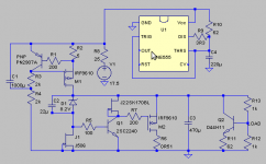
OK, here's the exact circuit I'm testing.
Attachments

ikoflexer said:I can confirm that pulling out J1 is detrimental; I left R5 in because I never got the time to experiment with it, but pulling it out probably will not affect much. However, I cannot say I've tried it.
It just helps a wee bit, especially with grounding. You can pull R5 off without any penalty.
salas said:What is the pinch off of J506?
It's better to use the 2SK170BL FET because the resulting zener current is ten times higher than with J506. I just used it because it was laying around.
Not only that. If the pinch off ain't low enough its ccs quality of performance will deteriorate and it will not help your tests. Please use a 2SK there if you have a spare.
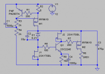
But if you were really worried about that you could put a resistor and a capacitor on the emitter of the NPN and raise the Vds across the FET. Then you would not need to worry about the pinch-off voltage.
Actually I think that's a good idea, because then you have a way to trim the output voltage. 200R in parallel with 3800u would give you about 3V across the FET without sacrificing low-frequency performance.
Actually I think that's a good idea, because then you have a way to trim the output voltage. 200R in parallel with 3800u would give you about 3V across the FET without sacrificing low-frequency performance.
jwb said:But if you were really worried about that you could put a resistor and a capacitor on the emitter of the NPN and raise the Vds across the FET. Then you would not need to worry about the pinch-off voltage.
Actually I think that's a good idea, because then you have a way to trim the output voltage. 200R in parallel with 3800u would give you about 3V across the FET without sacrificing low-frequency performance.
The way it was I was naturally worried about pinch off. It got it designed under a minimal component idea and to recycle spare 2SKs remaining from the RIAA circuit matching process. This is a nice idea to lift the emitter. 2 more passive components, no big deal. How is the transient performance with the large cap and resistor lifting the emitter? How much ESR did you simulate for it?
jwb said:This is measurably superior. I believe it's because of the higher Vds across J1.
Looks compact and business like. A hint on the measurements you got?
I just measured the output impedance with a sine wave load of 9mA RMS on top of a DC load of 65mA. Output impedance was below 10mOhms from 20 to 40k. Anything lower is below my ability to measure.
Didn't simulate it, and when I built it I used an ordinary NHG capacitor (standard ESR).
If you're just rolling in K170s, mail them to me 🙂 I only have 13 left.
Didn't simulate it, and when I built it I used an ordinary NHG capacitor (standard ESR).
If you're just rolling in K170s, mail them to me 🙂 I only have 13 left.
Did you see for regulation too? Or transient step? Sadly I got a small stash left from the 100 batch that I got from Spencer for $37. And I am using them for my phonos and here and there all the time. Maybe Spencer has got more.
Spencer's market section thread.
Spencer's market section thread.
jwb, this latest moddification degrades regulation both in simulation and in the real circuit. Perhaps someone can confirm either case. I have applied the modification you suggested to the circuit salas presented earlier, and not to your 12V circuit (I don't have those parts on hand); at the moment my interest is in a higher regulated voltage (24-25V).

ikoflexer said:jwb, this latest moddification degrades regulation both in simulation and in the real circuit. Perhaps someone can confirm either case. I have applied the modification you suggested to the circuit salas presented earlier, and not to your 12V circuit (I don't have those parts on hand); at the moment my interest is in a higher regulated voltage (24-25V).
Define "regulation"? Output transient response or something?
How about exchaning Q1 with a mosfet? You get more voltage drop for free, just add the drop the zener value. I've done it with 9610 and zvp3306 successfully in my own reg.
Rüdiger
Rüdiger
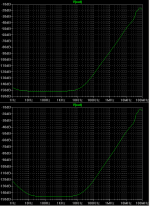
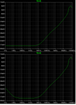
jwb said:Here's the simulator output for ripple rejection. The grounded emitter (original) on the top, the AC emitter lift (current) on the bottom. I agree that the simulator makes it look worse, but on the bench it measures better.
Any chance of showing the ripple rejection output with R3 (from post 241) replaced by a 2sk170 ccs?
- Home
- Amplifiers
- Power Supplies
- Best low noise regulator?