You want the lowest Rdc in your PSU. So, yes both chokes 8H. When we use tube rectification and a pure passive supply, lowest Rdc is the way to go...as the tube rectifier already have high resistance...
...and lowest inductance which is just giving enough ripple rejection, this will help enormously to avoid resonances which need to be damped again etc.
The result is a very high dynamic PSU with very nice micro resolution. A lot Lifelike and transparent.
...and lowest inductance which is just giving enough ripple rejection, this will help enormously to avoid resonances which need to be damped again etc.
The result is a very high dynamic PSU with very nice micro resolution. A lot Lifelike and transparent.
ESR Meter
under this very old website under
Repairing Switched Mode Power Supplies (SMPS) | All About Circuits
I read this:
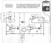
A very useful tool in checking and diagnosing electrolytic capacitors is an ESR meter. This tool allows for a quick check of all electrolytic capacitors without removing them from the circuit. I built myself an ESR meter based on this article which is itself a practical building of a design published by the Italian magazine Nuova Elettronica N212 as kit 1518. I made some modifications (which I think are improvements) to that design and the device has been very useful to me in repairing power supplies. An ESR meter does not measure capacitance but ESR (duh!) which is a very good indication of a capacitor's health and well-being. I recommend this tool and understanding how it works to anyone who will be repairing power supplies. Besides this one there are plenty of designs out there which can be easily and cheaply built by the amateur. One thing I like about this one is that it signals if the cap is shorted. This is very important because a shorted cap looks ideal with regards to ESR. The building of such an ESR meter would be a worthwhile project for anyone who does not own one.
maybe of interest
Esr tester for capacitor
Nuova Elettronica
Components from attached schematic
R1=1K5, R2,R3,R4,R5=10K, R6=68K, R7=4K7, R8=12K
R9,R11=1K-1%, R10,R12=22-1%,R13,R14=1K
R15,R16,R17=47K, R18=15K, R19=680
R20=2K2, R21=20K TRIMMER
C1,C2=1uF electrolytic
C3=1NF POLY, C4=100NF POLY, C5,C6=1microF POLY
DS1,DS2=1N4007, DS3=1N4148, DL1=LED
TR1,TR3=BC547, TR2=BC557, IC1=TL084
S1=SWITCH
under this very old website under
Repairing Switched Mode Power Supplies (SMPS) | All About Circuits
I read this:
A very useful tool in checking and diagnosing electrolytic capacitors is an ESR meter. This tool allows for a quick check of all electrolytic capacitors without removing them from the circuit. I built myself an ESR meter based on this article which is itself a practical building of a design published by the Italian magazine Nuova Elettronica N212 as kit 1518. I made some modifications (which I think are improvements) to that design and the device has been very useful to me in repairing power supplies. An ESR meter does not measure capacitance but ESR (duh!) which is a very good indication of a capacitor's health and well-being. I recommend this tool and understanding how it works to anyone who will be repairing power supplies. Besides this one there are plenty of designs out there which can be easily and cheaply built by the amateur. One thing I like about this one is that it signals if the cap is shorted. This is very important because a shorted cap looks ideal with regards to ESR. The building of such an ESR meter would be a worthwhile project for anyone who does not own one.
maybe of interest
Esr tester for capacitor
Nuova Elettronica
Components from attached schematic
R1=1K5, R2,R3,R4,R5=10K, R6=68K, R7=4K7, R8=12K
R9,R11=1K-1%, R10,R12=22-1%,R13,R14=1K
R15,R16,R17=47K, R18=15K, R19=680
R20=2K2, R21=20K TRIMMER
C1,C2=1uF electrolytic
C3=1NF POLY, C4=100NF POLY, C5,C6=1microF POLY
DS1,DS2=1N4007, DS3=1N4148, DL1=LED
TR1,TR3=BC547, TR2=BC557, IC1=TL084
S1=SWITCH
Attachments
Hi Blitz,
Thanks for the Cde advice, will try it.
Have you tried Scr tin foil too as dc blocker output of a tubed pre or dac instead OT ?
I m testing some FT lytics caps as well, did you find great differences with the Mundorfs?
Btw if some have advices about diodes for rectifier in tubes supply, heater and B+ ? A little off topic, pm please if you prefer.
Last edited:
An ESR meter is of limited use to be honest. Once you are used to the readings it can give you some idea for power supply capacitors. It is of zero use for coupling capacitors and many aspects of bypass capacitors.
What you need mostly for power supply capacitors are a pair of eyes (to inspect seals and case), and an oscilloscope so you can see the waveform as the equipment runs - coupled to an effective brain with some experience.
For coupling and bypass capacitors you really need to measure the capacitance (of course) and the dielectric absorption at different frequencies. It is critical you measure components at the frequencies of operation.
Testing capacitors in circuit is pointless unless they have a major fault. But other parasitic effects and paralleled components can throw off your readings. You only really know what you are measuring if the component is isolated, at least one terminal completely disconnected. There isn't an easy way out everyone seems to be searching for. Like the magic, in-circuit ESR tester for example. Dangerous for amateurs since the capacitors can hold a charge and discharge into your tester. Dangerous because you don't know what you are really measuring (you have an intent and assume you doing things properly), plus you don't know what numbers to expect and what they really mean. When do you know when a capacitor is bad? What frequency does it operate at, and what frequency did you just measure it at?
There is no magic instrument that will give you a number indicating the part is good or bad (or how good is it?). Parts typically are somewhere in between good and bad. It also depends on the dielectric used in the capacitor and construction. Different capacitors behave differently and have characteristics suited for various applications. Leakage current is another issue an ESR meter may not address. That's what can make capacitors go BANG!!!
Doing this work does involve some skill and a lot of knowledge. It takes university or some collage courses to really understand a capacitor and how it works, plus you need to understand failure modes. The average person who is skilled at other things is not well suited to this work, and from experience over the years, makes more mistakes than correct decisions. Sadly, after reading some internet "information" many are convinced they have done the job as well as a professional. They will not accept the fact that many times, they picked the wrong capacitors, maybe damaged the PCB or terminal strips and generally increased the costs of servicing their equipment.
How do they rip themselves off? Reduced reliability and reduced performance (but I used the best capacitor!) for the life of the equipment. Guess why I don't do my own accounting or legal work? How about rebuilding my car's engine ( I do know how and have done it before - successfully)? Because I am not up to date, don't have the tools, and do not know about the little things that make a big difference. I always use a professional in their field. They ave always saved me money and their work has been at least correct.
I do not own an ESR meter. I do own and use LCR maters that do measure parts for parameters that actually matter - and at the frequencies the parts really operate at. Sadly, this is more specialized equipment costing thousands of dollars. They still don't give me a go / no-go answer, the results need to be interpreted and compared to what that component type is expected t perform like. There is no "best" capacitor brand or type. It all depends on application, and the part must fit (physically) where the old one did. You also can't massively increase capacitance values. There are pros and cons to larger capacitance values, and often the designers have picked the right value in a "happy spot" for the application. An internet "star" will never know enough to second guess an engineer who has trained for the job, and the circuit in question was likely peer-reviewed at the company they work at.
Anyway, just try and be realistic about what you know, and what the equipment you have is really telling you. Don't assume you have used the equipment correctly without training and some research and that does not mean "white papers" (they are just advertising a point of view). Sounds like work? No, it's education needed to help you do the work correctly. The less you know, the easier something seems to be.
-Chris
Nicely said Chris. I hope it doesn't fall on deaf ears, you know, the ones that think all they need is there ears.
🙂
Thanks cbdb.
Somehow I don't think that the audience you are referring to tends to read much, and they won't get through that post. It is longer than I intended when I started writing.
Thanks cbdb.
Somehow I don't think that the audience you are referring to tends to read much, and they won't get through that post. It is longer than I intended when I started writing.
i once repaired a Fisher 500 receiver, one of the output tubes was red plating, so i went ahead and replaced an EROS coupling cap to fix the problem.....
i wanted to know what was wrong with the cap, i used my ESR meter and the cap measured as per label, so i took out my megger and tested, can't find anything wrong with it....
how do you explain that? except to say maybe the coupling cap caused the tube to oscillate and draw large plate currents maybe.....the other three caps were just fine...
But I have to say that ESR-meter is 'a must' if we repair something (or service). It saves tonnes of time. When I do a repair job I use an ESR-meter 98-99% of the time (and it is of an in-circuit type) and only 1-2% of the time I use my LCR meter.I do not own an ESR meter. I do own and use LCR maters that do measure parts for parameters that actually matter
Last edited:
But I have to say that ESR-meter is 'a must' if we repair something. It saves tonnes of time. When I do a repair job I use an ESR-meter 98-99% of the time (and I don't have to unsolder caps from a PCB) and only 1-2% of the time I use my LCR meter.
i agree, even for those stuffing boards, these testers are very useful also, i test all parts that go into my boards before soldering them in and any out of spec parts are set aside....
- this means you waste a lot of time doing service or repair.I do not own an ESR meter. I do own and use LCR maters
anatech is well experienced as a service agent for commercial stuffs, he knows his thing, just that this esr bussiness is of a recent vintage....
i will try any new technology if it eased my life on my work bench...
i will try any new technology if it eased my life on my work bench...
Red plating tube is mostly caused by leaking coupling caps introducing pos grid voltage. Leaking caps are not found with an ESR meter. As Chris wrote, this is not the universal tool to check caps.i once repaired a Fisher 500 receiver, one of the output tubes was red plating, so i went ahead and replaced an EROS coupling cap to fix the problem.....
i wanted to know what was wrong with the cap, i used my ESR meter and the cap measured as per label, so i took out my megger and tested, can't find anything wrong with it....
how do you explain that? except to say maybe the coupling cap caused the tube to oscillate and draw large plate currents maybe.....the other three caps were just fine...
I use the Ee DE 5000 lcr meter. Was around 100 Euro and measures between 100hz and 100khz. It gives you not only ESR but capacitance, inductance, cap grade / tangens
When you got exactly the same rated caps, so size and Voltage rated the same, typically the lower value esr amd higher value tan / grade will sound better. In the highest quality department, they measure very similar, there your ears need to decide. You measure at the frequency of their use, so power supply caps at 100hz...and for big capacitances you might need the external psu to charge them.up or fresh batteries and patience
When you got exactly the same rated caps, so size and Voltage rated the same, typically the lower value esr amd higher value tan / grade will sound better. In the highest quality department, they measure very similar, there your ears need to decide. You measure at the frequency of their use, so power supply caps at 100hz...and for big capacitances you might need the external psu to charge them.up or fresh batteries and patience
Hi Blitz,
Thanks for the Cde advice, will try it.
Have you tried Scr tin foil too as dc blocker output of a tubed pre or dac instead OT ?
I m testing some FT lytics caps as well, did you find great differences with the Mundorfs?
Btw if some have advices about diodes for rectifier in tubes supply, heater and B+ ? A little off topic, pm please if you prefer.
I tried aboit 20 different silicon diode types before switching to tubes rectifiers. My favorites were in the end hexfreds. Followed by Sic and germanium diodes, whuch can sound really tube like amd very nice when you find the right voltage types.
I tried on DC blocking caps / coupling caps a lot. Jupiter copper in wax HV was my winner above Duelund CAST followed by Miflex Kpcu1 which is the price /performance winner of all caps tried and heads and shoulder above Mundorf.
Red plating tube is mostly caused by leaking coupling caps introducing pos grid voltage. Leaking caps are not found with an ESR meter. As Chris wrote, this is not the universal tool to check caps.
no one claims that the ESR tester is a universal thing...not me....
but ESR testers are here to stay and i might as well use them...
btw, this is the first and only time i encountered a red plating caused by a cap that worked fine in another amp....but to be safe i binned that cap just the same...
My point was that the ESR-tester did not find the fault in case of some leakage - which may be quite small to make your tubes glow.
Hi Tony,
Some capacitors break down at higher voltages. I bet that is what you were experiencing.
-Chris
Some capacitors break down at higher voltages. I bet that is what you were experiencing.
-Chris
Thanks Blitz for the tips. 🙂
I have to dig a little about this LT4032 ideal diode bridge as well for the filament. I saw Member Prazi is proposing boards with the dip chip version.
I have to dig a little about this LT4032 ideal diode bridge as well for the filament. I saw Member Prazi is proposing boards with the dip chip version.
Hi Vovk Z,
The first thing you should do after a physical inspection with your eye balls is power the equipment up using a variac and watching the current. You hang your 'scope on the first filter in the power supply, and move it around to the various supplies while observing the waveform. Capacitors that might measure "good" have a distinctive waveform that may measure fine on an ESR meter. At this point I am so much further along in a repair than you are it isn't funny. That and I actually know the exact state of the capacitor in question without unsoldering anything. To use an ESR meter, you must unsolder one end of the capacitor to know for sure you are measuring the capacitor alone. Not unless you fly by the seat of your pants making assumptions left and right.
An ESR meter is just an AC ohmmeter. That's all it is. Capacitors are not rated in resistance, but rather capacitance. The other factors you must measure differently. The state of a filter capacitor, when it is bad enough shows up as a higher resistance. But, how high is too high? Then there is the question of how well calibrated the ESR meter is. The cheap ones aren't in case you are wondering.
The waveform across the capacitor is very sensitive to how the dielectric condition is. There will be a "pip" on the leading edge of the waveform that gets larger as the part deteriorates. New capacitors shouldn't show this at all. So this measurement is not only telling you about this part for certain, no matter the value you are seeing something easy to assess. I'll be done before you get the first capacitor tested (properly).
I do not need an AC ohmmeter to do my work. It may mislead you, and it is totally unsuitable for coupling capacitors and often decoupling capacitors. Keep in mind what you are trying to measure, and the circuit surrounding the part. That's why to measure a capacitor with any kind of meter, you have to disconnect one end. If I want to be certain about a capacitor, I use an LCR meter (HP 4263A in my case) and it never steers me wrong - ever. In fact, your oscilloscope is your best friend for bypass and filter capacitors. For other capacitors, the only substitute for a good LCR meter is replacement with the proper type of capacitor (and not by bridging it!).
The only instruments useful for parallel measurements in circuit are your voltmeter, and your oscilloscope. There is a reason why the ESR meter is a recent development, and it was created by hobbyists and maybe service people. You do not need an ESR meter or someone would have developed it in the 60's.
I think that an ESR meter has greater risks of leading people astray than pointing them in the right direction. If you don't disconnect the component you are measuring first using an ESR meter, you are making huge assumptions and showing that you don't understand how it works and what the meter truly is. If you do disconnect it first, a good LCR meter will tell you a lot more (so you grabbed the wrong instrument). DA is much more sensitive than ESR, so again you know more by using the correct instrument.
You don't need an ESR meter, it tells you very little about the capacitor you are looking at. What you do need is your oscilloscope, eyeballs and your brain. For a detailed look at a capacitor you actually need an LCR meter and look at the DA as well as capacitance. It goes without saying that the quality of the equipment you use has to be at a reasonable, minimal quality. I bought the HP 4263A when it first came out along with a 34401A DVM and Philips PM3070 scope (the DSO scopes were not good enough yet or I would have bought an HP). So these are close to 30 years old now and represent the best money I have spent for my bench. I have newer scopes and meters now (Keysight, which is HP) and those pay dividends, making my job easier and even allowing some measurements that are not possible with other equipment.
So no. I am not wasting any time at all. There is no substitute for knowing what you are doing and using your equipment properly. I guess the first rule is not to make any assumptions. The second is that you need to understand your test equipment and what you are actually measuring. There are no short cuts without making large assumptions. An AC ohmmeter (ESR meter) is of very limited use in reality. Call it by what it is, not a magic capacitor checker. It is an AC ohmmeter, period. The wrong tool for most jobs that promises things it can't deliver if you understand what you are doing with it.
-Chris
Why would you make that assumption? You are actually wrong.- this means you waste a lot of time doing service or repair.
The first thing you should do after a physical inspection with your eye balls is power the equipment up using a variac and watching the current. You hang your 'scope on the first filter in the power supply, and move it around to the various supplies while observing the waveform. Capacitors that might measure "good" have a distinctive waveform that may measure fine on an ESR meter. At this point I am so much further along in a repair than you are it isn't funny. That and I actually know the exact state of the capacitor in question without unsoldering anything. To use an ESR meter, you must unsolder one end of the capacitor to know for sure you are measuring the capacitor alone. Not unless you fly by the seat of your pants making assumptions left and right.
An ESR meter is just an AC ohmmeter. That's all it is. Capacitors are not rated in resistance, but rather capacitance. The other factors you must measure differently. The state of a filter capacitor, when it is bad enough shows up as a higher resistance. But, how high is too high? Then there is the question of how well calibrated the ESR meter is. The cheap ones aren't in case you are wondering.
The waveform across the capacitor is very sensitive to how the dielectric condition is. There will be a "pip" on the leading edge of the waveform that gets larger as the part deteriorates. New capacitors shouldn't show this at all. So this measurement is not only telling you about this part for certain, no matter the value you are seeing something easy to assess. I'll be done before you get the first capacitor tested (properly).
I do not need an AC ohmmeter to do my work. It may mislead you, and it is totally unsuitable for coupling capacitors and often decoupling capacitors. Keep in mind what you are trying to measure, and the circuit surrounding the part. That's why to measure a capacitor with any kind of meter, you have to disconnect one end. If I want to be certain about a capacitor, I use an LCR meter (HP 4263A in my case) and it never steers me wrong - ever. In fact, your oscilloscope is your best friend for bypass and filter capacitors. For other capacitors, the only substitute for a good LCR meter is replacement with the proper type of capacitor (and not by bridging it!).
The only instruments useful for parallel measurements in circuit are your voltmeter, and your oscilloscope. There is a reason why the ESR meter is a recent development, and it was created by hobbyists and maybe service people. You do not need an ESR meter or someone would have developed it in the 60's.
I think that an ESR meter has greater risks of leading people astray than pointing them in the right direction. If you don't disconnect the component you are measuring first using an ESR meter, you are making huge assumptions and showing that you don't understand how it works and what the meter truly is. If you do disconnect it first, a good LCR meter will tell you a lot more (so you grabbed the wrong instrument). DA is much more sensitive than ESR, so again you know more by using the correct instrument.
You don't need an ESR meter, it tells you very little about the capacitor you are looking at. What you do need is your oscilloscope, eyeballs and your brain. For a detailed look at a capacitor you actually need an LCR meter and look at the DA as well as capacitance. It goes without saying that the quality of the equipment you use has to be at a reasonable, minimal quality. I bought the HP 4263A when it first came out along with a 34401A DVM and Philips PM3070 scope (the DSO scopes were not good enough yet or I would have bought an HP). So these are close to 30 years old now and represent the best money I have spent for my bench. I have newer scopes and meters now (Keysight, which is HP) and those pay dividends, making my job easier and even allowing some measurements that are not possible with other equipment.
So no. I am not wasting any time at all. There is no substitute for knowing what you are doing and using your equipment properly. I guess the first rule is not to make any assumptions. The second is that you need to understand your test equipment and what you are actually measuring. There are no short cuts without making large assumptions. An AC ohmmeter (ESR meter) is of very limited use in reality. Call it by what it is, not a magic capacitor checker. It is an AC ohmmeter, period. The wrong tool for most jobs that promises things it can't deliver if you understand what you are doing with it.
-Chris
Hi. No, not quite so. I'll tell my way (+-), correspondingly to your text.Hi Vovk Z,
The first thing you should do after a physical inspection with your eye balls is power the equipment up using a variac and watching the current. You hang your 'scope on the first filter in the power supply, and move it around to the various supplies while observing the waveform. Capacitors that might measure "good" have a distinctive waveform that may measure fine on an ESR meter. At this point I am so much further along in a repair than you are it isn't funny. That and I actually know the exact state of the capacitor in question without unsoldering anything. To use an ESR meter, you must unsolder one end of the capacitor to know for sure you are measuring the capacitor alone. Not unless you fly by the seat of your pants making assumptions left and right.
An ESR meter is just an AC ohmmeter. That's all it is. Capacitors are not rated in resistance, but rather capacitance.
If the device "powers up" then I measure power supply DC voltages (all - input/output, etc), and AC ripple if there is a suspicion, with a multimeter. Usually, I don't need to see a waveform unless there is a reason to do a deeper investigation.
Then I may touch large caps with my fingers (if they are not high voltage), to check their temperature (a leakage current).
Then I use my in-circuit ERS meter (I don't unsolder anything). It gives me ESR and capacitance in turn. It has three modes: only ESR (main mode), only capacitance, and both in turn. Usually, 99%, if ESR is OK then capacitance is ok too. That's it.
If I have a bare PCB without a power supply module I may use my ESR-meter immediately, in-circuit.

- Home
- Design & Build
- Parts
- Best electrolytic capacitors