Nice Blitz, wow Alexander is getting famous now. I got 2 chokes from him too to test out on my 01a build.
Thanks again
Thanks again
PLease try a small C before the first choke if you use choke-input. LIke 0.33uf or 0.47uF, this will reduce the stress level for them considerably (see V(L1) in PSUD2) without changing the output voltage too much and you find the sweet spot of the great macro dynamic and authority of a LC-supply combined with the quietness and fine resolution and transient response of a CLC-suppply. ... there is a way to have both...I use Duelund CAST or Miflex KPCU1 there for low voltage and Mundorf silver/oil for 1000V.
Thanks for the advice Blitz. Question pls as the chokes are double bobbin do you think its good to connect the first choke in common mode style ?
Cheers
Cheers
Well, I think this is not a cmrr choke, so you could rather use it in differential mode...see jacmusic:
Empty Page
I tried that, difference is rather small to be honest...but complexity to do mistakes when building it is high...I did a couple of cabling errors in the beginning and melted down a power transformer...be careful...
More important is the rdc of your chokes. If they are smaller designs with higher rdc like 150ohm, you want to have the two coils in parallel and bring resistance down to 37ohm, which really make a big difference in sound....much better dynamics, resolution, life-like athmosphere than the series connection (if series rdc becomes to high).
It is very important to have low series rdc, no matter what PSUD2 tells you. Just try and listen and you ll see. 20 to 40 ohm is my target for HV chokes...and for filament chokes around 100-200mohm. If this brings you below critical inductance, give it a bleeder resistor and increase current. This sounds significatly better than staying with 150ohm series resistance.
If you go below those values in rdc, you loose tone and hear the resonance. But we are here in the tuning of the PSU where PSUD does not help you anymore. You have simply to try and listen, but with these values you have a good design idea.
Alexander has developed a new tool which is an excel spreadsheet for designing chokes to your specific needs incl. predection of resistance, inductance and flux density. So, you can tell it what you really will use it for, so the first choke of an LCLC supply has a totally different design limits compared to the second L where you have no AC-component across the choke which has immediate effect on the possible RDC and/or flux density or coes size etcetc.
This helps enourmously to design lowest Rdc chokes with sufficient Indusctance without using monster cores.
Last edited:
PLease try a small C before the first choke if you use choke-input. LIke 0.33uf or 0.47uF...
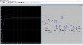
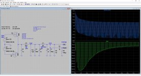
That's what I did for my preamp: playing with that small C, you can go all the way from CLC (top trace, 4.7uF) to LC (bottom 3 traces, 0, 0.22u & 0.47u). Beware the resulting voltages also vary by quite a bit, from Vac to Vac*SQRT(2); and the current, inversely.
Attachments
More importantly, you want to look at the AC- voltage across L2 in your schematic (so your choke-input choke). You change the stress level dramatically for the choke if the first C becomes bigger...
...in return you need to look at the current spikes and form of your transformer...you basically stress the transformer enourmously more when going to pure CLC...so the trick is, to find a good compromise and give the choke AND the transformer a nice, less stressfull environment to work in with lowest EMI.
In your case i would bet its a 0.22 or 0.33uf cap. Why dont you just pit a little switch into your psu, so you can switch those values in and out without even powering the amp off ? Thats what I do to find the right value...and as we talk about small differences in value, HV is not changing a lot (more than 0.47uf in your case will sound not so good anymore, you loose the choke input advantages at that point, things will sound less authentic, less dynamic, less real).
300R choke is not a good idea...this only looks good in the simulator, but sounds boring and liveless...eats too many transients and micro resolution, let alone macro dynamics...if this is a dual coil design, parallel the coils, so you got 75ohm and 5 H which is for the indicated 32mA /7k resistor anyhow a much better value. And a LCLc has in the end no ripple left. plus you want more a 50uF and 300uF cap nefore and after L1 to improve impulse response...
Last edited:
... you want to look at the AC- voltage across L2 in your schematic (so your choke-input choke)...
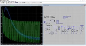
The voltage is OK, green trace, 2:1; the current is more scary, blue trace, 10:1, with the 0.1uF I chose... 🙂
With a LC filter, the head L is 10% science, i.e. L>>>L(crit) = RL/1000, DCR, etc.; I had 1 case of an inductor buzzing like hell with these sciences.
Then I figured there must be 90% voodoo, i.e. Imax>>>Iactual, size & weight (indicative of the copper & iron structure, the bigger the better), look (indicative of the care the part is designed and built). After I started applying the voodoos on top of the sciences, I no longer have any case of buzzing. The L2 in the example, I picked it up myself in Shenzhen (CN) for 10 bucks, and it's quiet as a grave.
Attachments
Hi Blitz,
Thank for the advice again. My chokes are wound to 32H 50ma each if connected in series RDC is around 130 ohms. My intention for the PS is to go LcLc with AZ1 as the rectifier. If I go parallel Rdc will be half but inductance will drop to around 7-8H. Original idea was to use lower value of capacitors. Perhaps can adopt your idea of parallel connection for the first choke ??? Your thoughts pls.
Thank you
Hi, if i didnt want to spend 60-100aud per cap when dealing with a 100 or 150uf, is there such a thing as a budget friendly option that doesnt sacfrifice too much on the audio side of things? IE going a non polarised 100v cap option?
I've only ever constructed some basic BSC's so i honestly have no idea.
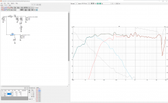
I've attached my fast crossover i'm going to build for reference incase people are interested what im using it in.
I've only ever constructed some basic BSC's so i honestly have no idea.
I've attached my fast crossover i'm going to build for reference incase people are interested what im using it in.
Attachments
Hi Blitz,
Thank for the advice again. My chokes are wound to 32H 50ma each if connected in series RDC is around 130 ohms. My intention for the PS is to go LcLc with AZ1 as the rectifier. If I go parallel Rdc will be half but inductance will drop to around 7-8H. Original idea was to use lower value of capacitors. Perhaps can adopt your idea of parallel connection for the first choke ??? Your thoughts pls.
Thank you
That is a perfect example.
Your 130 ohm choke in series has 65 ohm per winding (65+65). If we now parallel those windings, you get a 32.5ohm choke. Each winding can stand 50mA, so you now can stand 100mA actually. Your inductance is now 8H. I did exactly this with one of Alexanders Nano chokes.
Depending on the current and voltage needs of your circuit, you introduce a bleeder resistor which makes your chokes inductance high enough, like 50mA which brings you to the critical inductance of 8H where you no longer have a CLC setting. A small 0.47uF before the first choke is a good starting point. I guess you wanr the second choke for LCLC ? than do the same again, 8H as well and 130uF.
In any case, I would use the CDE 947D 130uF (130uF as this is the smallest value, normally you want a chain like 0.5uF - L1 - 30uF - L2 - 130uF here, but I would go for two times 947D) those 60 Euro per piece have no real alternatives and are more than worth it.
Sometime there are other dc-link caps on ebay from kemet and others as NOs or used items...so, if you want to sacrifies sound and spend less money in the beginning and understand how much better a dc-link polyprop cap is, you can try that...in the end you ll buy the cde anyhow and spent more money...my grandpa said always: We are too poor to buy cheap.
If you want to feel like you saved a lot of money...have a look at the CDE 947D in the Aries cerat stuff...and a look at their price list (xxx.xxx Euros...per piece): Bilder Aries Cerat ...great guys btw...I had a very open exchange with their developer, very open minded to share and learn as well stuff from the Diyaudio community
Last edited:
Hi, if i didnt want to spend 60-100aud per cap when dealing with a 100 or 150uf, is there such a thing as a budget friendly option that doesnt sacfrifice too much on the audio side of things? IE going a non polarised 100v cap option?
I've only ever constructed some basic BSC's so i honestly have no idea.
I've attached my fast crossover i'm going to build for reference incase people are interested what im using it in.
I would use Mundorf bipolar/plain smooth foil ECap70 | Mundorf EB GmbH two 47uf with connecting them reverse ro each other, like the old Blackgate bipolar trick.
The voltage is OK, green trace, 2:1; the current is more scary, blue trace, 10:1, with the 0.1uF I chose... 🙂
With a LC filter, the head L is 10% science, i.e. L>>>L(crit) = RL/1000, DCR, etc.; I had 1 case of an inductor buzzing like hell with these sciences.
Then I figured there must be 90% voodoo, i.e. Imax>>>Iactual, size & weight (indicative of the copper & iron structure, the bigger the better), look (indicative of the care the part is designed and built). After I started applying the voodoos on top of the sciences, I no longer have any case of buzzing. The L2 in the example, I picked it up myself in Shenzhen (CN) for 10 bucks, and it's quiet as a grave.
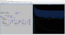
If you do your simulation comparison with the same cap values you used before, but just stay in one picture with the V(L2) and in a second picture I(T1), we ll learn something. Then you can see nicely the game of giving less stress to the choke (when the first caps grows) vs. increasing the stress to the transformer at the same time...
Besides manufacturing topics, the ratio of AC-voltage vs. DC-current in the first choke is important to understand when having a buzzing choke...so, the more DC-current there is, the more the choke gets clamped together by the current and the quieter it will become. The lower the inductance, the more important this factor becomes.
Last edited:
I meant V(L1) and I(V1), so the later one. If you now do the same sim with 1uf and with 4.7uF, you will see the effect.
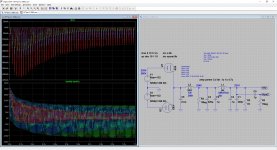
Thats a very nice ilustration. No, nothing to worry about, but it explains nicely why C1 has such a big effect on sound and how the stress is moved from the choke to the transformer:
We move in your example stress level choke from 360Vpp down to 70Vpp and increase the stress level of the transformer at the same time from 40mA peak to 240mA peak...
We move in your example stress level choke from 360Vpp down to 70Vpp and increase the stress level of the transformer at the same time from 40mA peak to 240mA peak...
Last edited:
That is a perfect example.
Your 130 ohm choke in series has 65 ohm per winding (65+65). If we now parallel those windings, you get a 32.5ohm choke. Each winding can stand 50mA, so you now can stand 100mA actually. Your inductance is now 8H. I did exactly this with one of Alexanders Nano chokes.
Depending on the current and voltage needs of your circuit, you introduce a bleeder resistor which makes your chokes inductance high enough, like 50mA which brings you to the critical inductance of 8H where you no longer have a CLC setting. A small 0.47uF before the first choke is a good starting point. I guess you wanr the second choke for LCLC ? than do the same again, 8H as well and 130uF.
In any case, I would use the CDE 947D 130uF (130uF as this is the smallest value, normally you want a chain like 0.5uF - L1 - 30uF - L2 - 130uF here, but I would go for two times 947D) those 60 Euro per piece have no real alternatives and are more than worth it.
Sometime there are other dc-link caps on ebay from kemet and others as NOs or used items...so, if you want to sacrifies sound and spend less money in the beginning and understand how much better a dc-link polyprop cap is, you can try that...in the end you ll buy the cde anyhow and spent more money...my grandpa said always: We are too poor to buy cheap.
If you want to feel like you saved a lot of money...have a look at the CDE 947D in the Aries cerat stuff...and a look at their price list (xxx.xxx Euros...per piece): Bilder Aries Cerat ...great guys btw...I had a very open exchange with their developer, very open minded to share and learn as well stuff from the Diyaudio community
Hi Blitz,
Thanks again for the advice, so you saying to connect both chokes in parallel ? In any case I will experiment with different connection & hear how they sound like. Will order some D Link to try out as well.
Many thanks again
Hi,
No, that is not what I meant. I understood from you that you got dual coil designed chokes from Alexander, right ? All of my chokes from him are dual coils, like the lundahls.
So, on ONE choke you can connect the two coils either in series or in parallel or as CMRR or Differential choke. These are the four choices you have for ONE choke.
All I suggest is, that you connect the two COILs (not chokes (!)) of ONE Choke in parallel instead of connecting them in series....beaware of the correct orientation of the coils + goes to +...have a look how lundahl does this...same here.
-----------
You do this for both of your Chokes.
Than you build a LCLC-PSU with them, so the two chokes are in series, but after each choke a cap goes to ground.
And finannly, you put the small 0.5uF infornt of everything (to ground).
Last edited:
Hi Blitz yes they're build just like Lundahl with twin coils. What Im asking is do you suggest to connect the 2 coils in parallel to make 8H for both chokes ? Meaning LcLc of 8H per choke. Hence my reply was I'll try different ways including series connection for both chokes or parallel for both chokes or parallel for first choke & series for 2nd choke etc.
Many thanks again
Many thanks again
- Home
- Design & Build
- Parts
- Best electrolytic capacitors