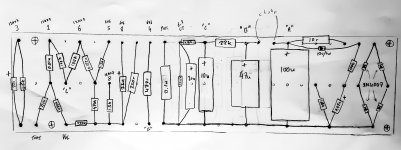
Pretty good circuit. I'd add .01uF 3kV cer caps from each AC wire (hot and cold) to the earth ground wire, which should tie to the chassis right where it comes in, and put another one across the secondary of the power tranny. Since it looks like you've got a voltage regulator circuit (?) I would replace the choke with a resistor, if you can afford to drop another 20V or so. I worry about the power dissipation in the 6V6 bias pot. I haven't done the math but that could be an issue.
If you put another ,01uF 3kV cap across the power switch, the switch will last longer and not make a pop sound when you turn off the amp. Just a personal preference, I like to draw the schematic such that all secondary power supply grounds are tied together, before they get to a single "star center" ground symbol, since that's important in how you wire it for minimal hum. I'd also put a .01uF 3kV cap across each filter cap so Rf frequencies are shorted out. Also, if you put a 680pF cap across the 1M input resistor, you'll have an Rf low pass filter that will put you down 3dB at 19.5kHZ, assuming a 12kohm guitar pickup source impedance (most are between 7k and 10K ohms). Good for when the guitar acts as an antenna and picks up Rf energy out of the air, which will then get detected by the circuit acting in a non-linear way at Rf frequencies, thereby generating intermodulation distortion products some of which will be in the audio frequency range.
If you put another ,01uF 3kV cap across the power switch, the switch will last longer and not make a pop sound when you turn off the amp. Just a personal preference, I like to draw the schematic such that all secondary power supply grounds are tied together, before they get to a single "star center" ground symbol, since that's important in how you wire it for minimal hum. I'd also put a .01uF 3kV cap across each filter cap so Rf frequencies are shorted out. Also, if you put a 680pF cap across the 1M input resistor, you'll have an Rf low pass filter that will put you down 3dB at 19.5kHZ, assuming a 12kohm guitar pickup source impedance (most are between 7k and 10K ohms). Good for when the guitar acts as an antenna and picks up Rf energy out of the air, which will then get detected by the circuit acting in a non-linear way at Rf frequencies, thereby generating intermodulation distortion products some of which will be in the audio frequency range.
Ditto What Bob says.
- the VVR with .47 cap will kill enough ripple to make the choke a weight & cost liability
- the .022 cap will let thro all frequencies of interest, reduce to .010 to tighten up response if necessary; build it and see 1st.
- the VVR with .47 cap will kill enough ripple to make the choke a weight & cost liability
- the .022 cap will let thro all frequencies of interest, reduce to .010 to tighten up response if necessary; build it and see 1st.
I worry about the power dissipation in the 6V6 bias pot. I haven't done the math but that could be an issue.
I've been worried about this as well. For about $5 a 5W single turn can be found on digikey. For the 12L6 I'm going to experiment with it's OK and from just a quick look, it appears as if the 6v6 is a lower current so I think it'll be alright.
Ditto What Bob says.
- the VVR with .47 cap will kill enough ripple to make the choke a weight & cost liability
- the .022 cap will let thro all frequencies of interest, reduce to .010 to tighten up response if necessary; build it and see 1st.
Quite possibly put a 0.01 in first and then aligator clip in another for testing? I'm just thinking might be easier to compare the two then.
I have played a bunch of champs and I am going to say my favorite circuit is the vibro champ AA764.
IMHO the biggest attribute is the speaker! In all the champs I have played I still prefer by far the original 8" Oxford AlNiCo. You can't touch them with anything made today, well at least what I have tried. This speaker has so much punch. I bought it for $400 and it's in immaculate condition. I love it so much, it's my favorite amp. Everywhere I go everyone offers me so much $$ for it and I just smile and decline.
As far as output tube I stick with the RCA grey glass and I have tried almost every variant.
When I got my 66 blackface Vibro-Champ there was an extra cap in the can not being used so I reformed it and added another RC network in the filter supply, the amp is dead quiet and I like the extra sag which only comes through when overdriven, when played clean the amp is super fast because it draws nearly a constant current due to it's class A operation.
It's sweet sustain all day long 🙂
There is so much you can do with this circuit, but at the end of the day the sound will be mostly dictated by your speaker choice. 10 or 12" has to be an option to consider if building your own cabinet.
The Jensen P10R is perhaps my favorite guitar speaker that I have 1st hand experience with. 10 inch, w. alnico magnet. The ceramic magnet version is about half the price and also sounds quite good. Many guitar amps that have 1Mohm volume controls also have a 100pF cap from the top to the wiper. This pumps up the high freqs a bit, unless the volume is maxed out. If the finished amp lacks high treble you might try adding that too. And the 50K feedback pot, I'd make that a 100K or 250K for a different sound. The bigger it gets, the less effect the bright control will have, but the overdrive distortion might be significantly better, if that matters.
Last edited:
If you really want the Champ sound and feel you must use a small speaker. The punchy speed from the 8" AlNiCo is what it's all about. An impedance switch and external speaker jack is all that's needed if 10"-12" speaker options are desired. I have tried my Champ through various 12" speakers and although it sounds fine it's doesn't have the same sound and feel as with the 8" speaker.
I don't get why people use 50-100 watt amps when playing through a PA. I actually don't think most guitarists understand their gear too much to begin with. It's funny how a little 5 watt amp through an 8" speaker can floor most amps when mic'd. For bluesy rock sort of tone of course. Dime the amp and use your guitars volume for a "dirt" control. With PAF humbuckers in a semi hollow guitar I use 0-3 on my guitar volume is for clean volume control, anything past that get louder and dirtier until about 8 and then it just gets dirtier. Some songs that I know won't have any fuzz I just walk back and turn the amps volume to 4 for great range of clean tones. Throw in some nice boost/compression and you have a very versatile amp that can scream and also clean up nicely, if you know how to use it.
I don't get why people use 50-100 watt amps when playing through a PA. I actually don't think most guitarists understand their gear too much to begin with. It's funny how a little 5 watt amp through an 8" speaker can floor most amps when mic'd. For bluesy rock sort of tone of course. Dime the amp and use your guitars volume for a "dirt" control. With PAF humbuckers in a semi hollow guitar I use 0-3 on my guitar volume is for clean volume control, anything past that get louder and dirtier until about 8 and then it just gets dirtier. Some songs that I know won't have any fuzz I just walk back and turn the amps volume to 4 for great range of clean tones. Throw in some nice boost/compression and you have a very versatile amp that can scream and also clean up nicely, if you know how to use it.
Hi Guys
Adding caps from the mains to chassis is asking for trouble. The correct way to eliminate ground hum and retain the AC safety ground is as follows:
Tie the safety ground to chassis on its own lug.
WIRE the amp ground as shown in TUT3 using the Galactic ground method. This means that the input and speaker jacks must be insulated from the chassis.
Connect the amp (signal) ground to chassis using a ground isolator-connect, comprised of a 100R, 100nF poly, and two anti-parallel diodes all in parallel. The R provides a DC ground path when no other devices are connected to the amp, but provides some isolation when other grounded devices are connected. The cap provides RF grounding. The diodes protect the R and C and limit ground-fault voltage differences. Because the ground-fault currents can be very high, the diodes must be high-current types and most often are in a bridge with the ACs tied together and DCs tied together.
It's also a good idea to add fusing to the secondary of the PT to protect the PT and downstream circuits. The single mains fuse only protects the main, not the PT.
Apart from this, the VVR has its own built-in compromises that can affect tone. For its protection, a diode should be added in series with the output, feeding the first filter cap. The loudness control range is compromised and only allows about 20dB reduction. 5W becomes 500mW which is still 97dB from a typical 12" guitar speaker. This is why Power Scale circuits provide over 44dB range so the player can decide how quiet "quiet" is. It is generally a bad idea to Scale the whole amp as tone always changes doing it that way.
The Champ circuit is inherently compromised by its single dual-triode tube. Modern forms like the Marshall C5 add another bottle which gives two more stages to do tonnes of things with. With four stages, you can retain the PA NFB loop if you wish for a tighter tone and stll have three stages for a very smooth distortion sound. Clean sounds are usually better too, using more stages since each stages adds its veil of tube character to the sound.
Even with the standard tube complement, the NFB can be eliminated and a reasonably tight sound retained in two different ways: use an OT with a UL tap, or add a feedback resistor just around the output tube. Either way lets you get more gain out of the second stage.
Have fun
Right, work has been MAHEM, so my layout remains an atrocious scribble and not fit for public consumption. *But* I think I have my head around how it will be built... sooooooo without further ado: PARTS ARE ORDERED!!!
No problem on the still unfinished schematic. You say you wanted a looser type of build this time, more experimenting, as your previous Lightning was a " by the numbers" build as you say. Experiment with different values of resistors and caps, both cathode bypass and coupling cap values and see what sounds good. It's fun to learn as you go with substituting values and hear the immediate results from a change you made. It's a nice change from running endless sims. Change power supply dropping resistors for different B+ voltages, change bias points, etc. Lots of possibilities as you can take parts of different versions and put them together for a "new" version. Maybe the "Lightreel Princeton" will be born.
Last edited:
About to solder and I'm concerned about the 6V6 bias grounding point - is it best to have it on the preamp or power amp "side"?
I'm guessing I have it wrong and it should be on the power side... or maybe even it's own ground point???
I'm guessing I have it wrong and it should be on the power side... or maybe even it's own ground point???
Last edited:
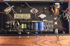
Some progress (pic attached)
Chassis is done and all hardware is mounted. I still haven't soldered as I plan on going over my layout one last time! I moved the 6V6 bias ground to the power side, but it's easily changed if it's not happy like that. Presence cap was moved to input ground side.
The electronics and chassis work was a lot quicker this time through, but as I'm building the cab myself it guess it will slow down overall. I'm planning a basic style combo in birch ply, covered in green tolex. Big enough (just) to take a 12", but I'll make a 10" baffle too.
Attachments
HELP!!!
It's not working. Just blowing fuses straight away :-(
Anyone any ideas? I've checked everything I can think of.
The only weird thing is that the 6.3 CT wire (green/yellow) is coming off the primary side of the PT. Maybe I should crack it open to see what's going on???
It's not working. Just blowing fuses straight away :-(
Anyone any ideas? I've checked everything I can think of.
The only weird thing is that the 6.3 CT wire (green/yellow) is coming off the primary side of the PT. Maybe I should crack it open to see what's going on???
Unhook stuff and go from there. Start at the trafo, measure voltages. If that's pjs then check your SC output. Hook up the gain stage.... Etc so forth. You'll be bound to see where its coming from.
Thanks jlangholz. I'll get on that. In the mean time I popped the covers of the PT... that green/yellow is definitely going to the primary side. Which makes no sense to me. Spec sheet definitely says it should be the 6.3CT (http://www.hammondmfg.com/pdf/EDB372BX.pdf).
I'll cut the connection to it and see what happens. Amp should work without a 6.3 CT? Just be quite hum-y... right???
I'll cut the connection to it and see what happens. Amp should work without a 6.3 CT? Just be quite hum-y... right???
Wow my mobile atuocorrect murdered that. check you DC outputs out of the trafo and go from there. If you're not sure about the CT you could always do a virtual CT with a couple resistors. This would work both if grounded it or elevating the supply with it.
If everything out of the DC stage is okay, like i (tried) to say, start hooking different stages up and you'll find where the short/miss wire is pretty quickly. Hook the heaters up to the tubes first maybe, check those. Make sure your rail voltages are kosher...etc.
If everything out of the DC stage is okay, like i (tried) to say, start hooking different stages up and you'll find where the short/miss wire is pretty quickly. Hook the heaters up to the tubes first maybe, check those. Make sure your rail voltages are kosher...etc.
With nothing connected the PT seems stable and the voltage is reading approx 650 and 6.4 which is what I expected.
I disconnected the suspect CT and made a virtual CT, the heaters work fine when connected, with B+ disconnected.
I bypassed the VVR.
But with the circuit connected it still doesn't seem happy: the PT gets very hot REALLY fast, and I can smell it... so I haven't dared run it for long.
I disconnected the suspect CT and made a virtual CT, the heaters work fine when connected, with B+ disconnected.
I bypassed the VVR.
But with the circuit connected it still doesn't seem happy: the PT gets very hot REALLY fast, and I can smell it... so I haven't dared run it for long.
You should really be using a variac and dim bulb tester for first starts, that aside it sounds like you have a dead short on the high voltage side if the heaters work in isolation. You need to go back over all your wiring and look for the mistake, or post some pics incase we can spot something.
- Status
- Not open for further replies.
- Home
- Live Sound
- Instruments and Amps
- "Best" Champ / Princeton schematic?