Correct me if I'm wrong here but if you're going to put the tone stack pre-output then you've got no real need to put a second gainstage in there. I thought that was always the traditional reason for putting it between two different gain stages, amplify the signal first and then recover all the loss with the second stage, feed it to a phase inverter...etc after that. At least that's the only topology I've ever seen......so...I got nothing hahaha.
Also good point on the cap on the mains. This was something I came across somewhere along the way and I was going to pick out an IEC plug with filtering already present to eliminate that from the chassis.
As far as RF goes I'm sure it won't hurt but I've found more issues in not having your axe set up properly than it being in the amplifier. Good shielded cables, foil innards on the pot cavity, and a capacitor across the pups was always a great way to get rid of it. Played across anything from original blackface's to new stuff and never had any problems after that.
I'm not sure how paul feels about it but I'm on the edge of flirting with complexity and versatility and the original "spirit" of the 5F2. I'm adding enough flexibility in there to change tubes and bias some but it'll all be inside the chassis. I DO remember him saying that "I don't want a panel full of switches and knobs" and I don't either.....you open the back up though....now that's a different story.
EDIT:
and I forgot about the reverb...yeah....not even going to touch that LOL. I've looked at lots of different reverb circuits just in browsing amp designs and...yeah...I'm leaving that alone. Maybe someday 🙂
This circuit has the magic. Great sound clean or over driven. It got to where I had too many amps so I sold this one. The guy who bought it emailed me later and said, "If you want it back you'll have to pry it out of my cold dead hand"...
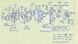
The zener in the Line Out circuit shorted and needed to be cut out. It was intended to protect external devices from overload. If you can't get the 6SJ7 pentodes (out of production but many surplus here in the U.S.) you could substitute a JJ EF806S (their version of an EF86), but may need to readjust the bias and plate load R for best results. If you replace the 6SJ7 with a 12AX7 circuit, you'll have less gain, but may still have enough. The output transformer was nothing special. It was the cheapest simplest single ended output xformer they had at Antique Electronics in Arizona, where I bought most of the parts. I forget what the primary impedance was, but whatever is appropriate for a 6V6. The 180 ohm R and 47uF cap set the "sag", which I never paid much attention to, but seemed to work well. Up stream from that I had two stages of RC filtering with larger caps. A single ended circuit has poor power supply rejection, so it's wise to have good filtering in the power supply before the "sag" RC.
The zener in the Line Out circuit shorted and needed to be cut out. It was intended to protect external devices from overload. If you can't get the 6SJ7 pentodes (out of production but many surplus here in the U.S.) you could substitute a JJ EF806S (their version of an EF86), but may need to readjust the bias and plate load R for best results. If you replace the 6SJ7 with a 12AX7 circuit, you'll have less gain, but may still have enough. The output transformer was nothing special. It was the cheapest simplest single ended output xformer they had at Antique Electronics in Arizona, where I bought most of the parts. I forget what the primary impedance was, but whatever is appropriate for a 6V6. The 180 ohm R and 47uF cap set the "sag", which I never paid much attention to, but seemed to work well. Up stream from that I had two stages of RC filtering with larger caps. A single ended circuit has poor power supply rejection, so it's wise to have good filtering in the power supply before the "sag" RC.
Attachments
Correct me if I'm wrong here but if you're going to put the tone stack pre-output then you've got no real need to put a second gainstage in there. I thought that was always the traditional reason for putting it between two different gain stages, amplify the signal first and then recover all the loss with the second stage, feed it to a phase inverter...etc after that. At least that's the only topology I've ever seen......so...I got nothing hahaha.
Also good point on the cap on the mains. This was something I came across somewhere along the way and I was going to pick out an IEC plug with filtering already present to eliminate that from the chassis.
As far as RF goes I'm sure it won't hurt but I've found more issues in not having your axe set up properly than it being in the amplifier. Good shielded cables, foil innards on the pot cavity, and a capacitor across the pups was always a great way to get rid of it. Played across anything from original blackface's to new stuff and never had any problems after that.
I'm not sure how paul feels about it but I'm on the edge of flirting with complexity and versatility and the original "spirit" of the 5F2. I'm adding enough flexibility in there to change tubes and bias some but it'll all be inside the chassis. I DO remember him saying that "I don't want a panel full of switches and knobs" and I don't either.....you open the back up though....now that's a different story.
EDIT:
and I forgot about the reverb...yeah....not even going to touch that LOL. I've looked at lots of different reverb circuits just in browsing amp designs and...yeah...I'm leaving that alone. Maybe someday 🙂
You need a certain amount of gain, and the position of the tone circuit doesn't change that need. These days there is a lot more Rf in the air, and light dimmers are particularly significant Rf generators for emissions conducted through the AC line.
The amps that are designed for output tube "rolling" have adjustments for bias, but I haven't seen one that also readjusts the output transformer primary impedance, so that can be pretty far off. If you're just swapping between the 6V6 and an EL84, that shouldn't be a problem. But the EL84 has lower max voltage specs, so watch out for that.
Very interesting thread, having built my own Champ/Priceton clone a while back i have a question.
What are the pros/cons of building the later style power supply with a CRC filter section, vs the early models with a CLC filter. I used 22uf-10k-10uf-22k-10uf in my build, but wondering now if i should go back and replace the 10k with a choke.
Cheers all,
Mark
What are the pros/cons of building the later style power supply with a CRC filter section, vs the early models with a CLC filter. I used 22uf-10k-10uf-22k-10uf in my build, but wondering now if i should go back and replace the 10k with a choke.
Cheers all,
Mark
The feature of a choke is that it drops a lot less DC voltage than a resistor feeding a cap, that would have the same filtering effect. So it's more efficient. You don't waste nearly as much power on a resistor (maybe 5 - 10 watts). But, it forms a two pole filter in conjunction with the cap it feeds, and if the two aren't calculated properly for a good transient response, you can get overshoot on start up and/or turn-off that could send a pretty big voltage transient out into the circuit, which at turn on is a very light load, since the tubes aren't conducting yet. Refer to 2 pole LC filters for crossovers, and you'll note that the response shape and roll off characteristic is only right when the L and C and load are all balanced a certain way. When the load, as seen by the reactive components changes, the balance is thrown off. This will likely be hard to notice in a power supply unless it generates a voltage transient that blows something up.
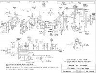
Back in the early days of guitar amps, the biggest caps you could get might have been around 20uF, so chokes made better sense. Now I just get a power tranny that has an extra 50 or so volts more than I need, and split that up across 2 power resistors feeding caps. It works quite well and saves a bunch of space on the chassis (which is usually very crowded - especially when I build a stereo guitar amp).
Here's an amp I built recently. You can see how I did the power supply.
Attachments
The feature of a choke is that it drops a lot less DC voltage than a resistor feeding a cap, that would have the same filtering effect. So it's more efficient. You don't waste nearly as much power on a resistor (maybe 5 - 10 watts). But, it forms a two pole filter in conjunction with the cap it feeds, and if the two aren't calculated properly for a good transient response, you can get overshoot on start up and/or turn-off that could send a pretty big voltage transient out into the circuit, which at turn on is a very light load, since the tubes aren't conducting yet. Refer to 2 pole LC filters for crossovers, and you'll note that the response shape and roll off characteristic is only right when the L and C and load are all balanced a certain way. When the load, as seen by the reactive components changes, the balance is thrown off. This will likely be hard to notice in a power supply unless it generates a voltage transient that blows something up.
Back in the early days of guitar amps, the biggest caps you could get might have been around 20uF, so chokes made better sense. Now I just get a power tranny that has an extra 50 or so volts more than I need, and split that up across 2 power resistors feeding caps. It works quite well and saves a bunch of space on the chassis (which is usually very crowded - especially when I build a stereo guitar amp).
Here's an amp I built recently. You can see how I did the power supply.
You say the feature of a choke is it drops less DC voltage but you forgot to mention that choke's main feature is that it resists a change in current, so provides an additional type of filtering. After that initial transient you speak of that may or may not happen, the choke provides an additional element to the filtering of the power supply by smoothing out the ripple current because of this unique action only provided by chokes. Here is a good primer by someone else who could write a book. Your idea of having extra voltage offsets the part where he says sooner or later there will be too much voltage drop. You have a good case for not using a choke. Here is a good primer explaining the benefits of having one. Especially see " Why Use a Choke" section. Chokes Explained
A cap opposes a change in voltage and a choke opposes a change in current, so a filter with a choke(pi filter) will have less hum because of this double filtering element. This is a subject which is a personal choice, so not having a choke is just that, a personal choice. I only offer this to provide the other viewpoint. To each his own. Sure, you could just throw a bunch of 50uF caps at it, but some rectifier tubes can't handle those high values according to the data sheet.
Also an amp can be laid out so there isn't such a large space taken up by a choke. They are not anywhere near as large as the PT of the OT, or at least don't have to be. Nothing wrong with getting a slightly larger chassis either.
Thanks guys, i am familiar with chokes as i use them in almost every amp i have built. My question was specifically about the two versions of the Champ amp, has anybody any first hand experience with them both, and was there any noticeable sonic differences between them.
Wow guys, work has been mental so this dropped off my radar for a few days but I have so much to digest! Thanks for keeping this alive. I'll update my schematic with a few of the suggestions and hopefully finish my layout (a far trickier task than I imagined!).
Wow guys, work has been mental so this dropped off my radar for a few days but I have so much to digest! Thanks for keeping this alive. I'll update my schematic with a few of the suggestions and hopefully finish my layout (a far trickier task than I imagined!).
Good to see you're still alive 😀 Truth be told works been mental for me lately as well but this serves as a great way to decompress with your spirit of choice at the end of the day!
Sorry I forgot to mention that the choke directly helps do the filtering. I guess I thought that was obvious and was trying to make a different point. A resistor by itself does not help filtering, but when it affects the charging time constant of the cap that follows, it effectively does.You say the feature of a choke is it drops less DC voltage but you forgot to mention that choke's main feature is that it resists a change in current, so provides an additional type of filtering. After that initial transient you speak of that may or may not happen, the choke provides an additional element to the filtering of the power supply by smoothing out the ripple current because of this unique action only provided by chokes. Here is a good primer by someone else who could write a book. Your idea of having extra voltage offsets the part where he says sooner or later there will be too much voltage drop. You have a good case for not using a choke. Here is a good primer explaining the benefits of having one. Especially see " Why Use a Choke" section. Chokes Explained
A cap opposes a change in voltage and a choke opposes a change in current, so a filter with a choke(pi filter) will have less hum because of this double filtering element. This is a subject which is a personal choice, so not having a choke is just that, a personal choice. I only offer this to provide the other viewpoint. To each his own. Sure, you could just throw a bunch of 50uF caps at it, but some rectifier tubes can't handle those high values according to the data sheet.
Also an amp can be laid out so there isn't such a large space taken up by a choke. They are not anywhere near as large as the PT of the OT, or at least don't have to be. Nothing wrong with getting a slightly larger chassis either.
On the issue of rectifiers not liking charging big caps, that's why I always put a series resistor between the rectifier and the first big cap. It serves a current limiting function, while also getting the filtering off to a good start.
Sorry if I was unclear about this.
Yes, I saw the point you were making and just wanted to be sure of stating it's specific function as opposed to just "it helps in filtering".
I should have made that point about the reservoir cap as well. The max cap size given in the data sheets is only for when the rectifier tube is operated at the maximum rated current and minimum series resistance is connected. If the actual DC current is lower or the series resistor is higher, the max cap value given can be increased. With the series resistance you use, this allows for the reservoir cap to be larger than the given value in the data sheet. Nice design. Always enjoy and learn from your informative posts, Bob.
Now if only we could help mcandmar with his question as to the difference soundwise of the two designs. I do know the Champ 5E1 is a little different in that they take the plate and screen supplies after the choke rather than the usual way of taking the plate supply before the choke and screen after the choke. It appears that the plate voltage will actually be a couple of volts lower than the screen because the small DC drop from the OT will lower the plate by a couple of volts and the screen is connected directly to that node, so it seems there will be a small difference difference in the sound of the 6V6 maybe? The 5F1 is more conventional in that the plate is taken before the first dropping resistor and screen taken after, so it looks as if the voltage relationships between the two will be more conventional. Anyone else see it that way?
Last edited:
Sorry, should have given a reference to the two schematics.
View attachment Fender_champ_5e1_schem.pdf
View attachment Fender_champ_5f1_schem.pdf
View attachment Fender_champ_5e1_schem.pdf
View attachment Fender_champ_5f1_schem.pdf
That was exactly what i meant, thanks boobtube.
Just to add more confusion into the mix, i built mine as per the Princeton 5F2-A with the tone control between the two 12ax7 gain stages, and a cathode bypass capacitor on the 1st gain stage like the 5E1. There is at last half a dozen different variations of the Champ/Princeton so deciding which to build was the biggest challenge 🙂
Just to add more confusion into the mix, i built mine as per the Princeton 5F2-A with the tone control between the two 12ax7 gain stages, and a cathode bypass capacitor on the 1st gain stage like the 5E1. There is at last half a dozen different variations of the Champ/Princeton so deciding which to build was the biggest challenge 🙂
Attachments
The 5F1 makes sure the screen is at a lower voltage than the plate, which is considered the proper way to do it. The 5E1 does it the way many amps in the 40's and early 50's did it, which puts the screen grid at a slightly higher voltage than the plate (due to the drop in the OT primary winding). I don't know if this way has a better distortion sound when over driven, but I will say that there's a much better chance that the screen grid will glow red from dissipating more power than it's designed for. I would expect the 5E1 to burn out its 6V6 significantly sooner due to this. A screen grid has a max power dissipation spec., and it's usually approximately 5% of what the plate is running.
If someone gave me a 5E1, I would put a 470 ohm 2W resistor in series with the screen grid. This R would drop voltage as soon as current flowed, thereby reducing the voltage on the screen grid, and keeping the power dissipation from being too high.
The 5F2A circuit looks very good and reliable. One thing I'd change though is the heater circuit. Instead of grounding one side, I would put a voltage divider across the first filter cap, creating a +30 to +50 VDC tap, and tie that to one side of the filament winding. I'd also put a 10uF cap off that tap to gnd. For divider resistors, I'd use approximately 680K 2W and 75K 2W, or whatever gets you anywhere near +30VDC. This causes the cathodes of the tubes to be a minus voltage compared to the heaters, so less hum.
Also, the 22Kohm feedback R cleans up the sound a bit, but if you want more "color" or a different and possibly better distortion sound, you might try increasing that value to 100K or even higher. Gain will go up, and the speaker resonance will be less tamed. It's something to try. You might like it.
Last edited:
Interesting idea on the heater grounding. I went with the Tube Depot layout of grounding the heater winding via two 100r resistors.
Speaking of which, i'm not sure if its been mentioned in this thread already but TubeDepot has a lot of information on their kits available online which may be valuable to others.
I went pure DIY on my build, but i did buy the blank fiber board, standoffs, speaker, and a few other bits and bobs from them for this project.
https://www.tubedepot.com/products/tweed-5f1-vacuum-tube-amp-kit
I also added a 50k pot in series with the 22k feedback resistor with a switch to by pass it so i can adjust the feedback level, or disable the pot. In hindsight the effect isn't that great, a 100k pot may work better in that position.
Last edited:
The 5F1 makes sure the screen is at a lower voltage than the plate, which is considered the proper way to do it. The 5E1 does it the way many amps in the 40's and early 50's did it, which puts the screen grid at a slightly higher voltage than the plate (due to the drop in the OT primary winding). I don't know if this way has a better distortion sound when over driven, but I will say that there's a much better chance that the screen grid will glow red from dissipating more power than it's designed for. I would expect the 5E1 to burn out its 6V6 significantly sooner due to this. A screen grid has a max power dissipation spec., and it's usually approximately 5% of what the plate is running.
If someone gave me a 5E1, I would put a 470 ohm 2W resistor in series with the screen grid. This R would drop voltage as soon as current flowed, thereby reducing the voltage on the screen grid, and keeping the power dissipation from being too high.
Absolutely! That's what I was getting at when I pointed that out. The screen should always be at least a couple of volts lower than the plate, at least in pentode mode. And as a personal note, I usually have it about 4 volts lower for 300-350 volt supplies and around 5-8 volts for 400-450 volt supplies. There's not going to be enough loss of power by doing this but gives a little more safety factor for the screen which is the most common failure for power pentodes, so why not protect it a little more and sacrifice a small amount of power you won't even miss? I don't know why they would build this amp in the first place without lowering the screen grid voltage. I think at that time, they knew better. I see they did the same thing for the 5E2 Princeton. Even the 5C1 has a 25k dropping resistor between the screen and plate. Same for the 5C2 Princeton. Both models were a few years earlier than the 5E1.
Doing the resistor center tap thing is better. I should have mentioned that. The 50K pot added to the 22K R is only a small change. It's the ratio of the feedback R to the cathode R that it ties to that determines the feedback level and gain. Since you can't change the cathode R without changing the bias on that tube, it's the feedback R that you might want to take much higher, to get any noticeable effect. You can go as high with that as you want. I eliminate it entirely in all my designs. None of my guitar amps have any negative feedback, and they sound great to my ear.Interesting idea on the heater grounding. I went with the Tube Depot layout of grounding the heater winding via two 100r resistors.
Speaking of which, i'm not sure if its been mentioned in this thread already but TubeDepot has a lot of information on their kits available online which may be valuable to others.
I went pure DIY on my build, but i did buy the blank fiber board, standoffs, speaker, and a few other bits and bobs from them for this project.
https://www.tubedepot.com/products/tweed-5f1-vacuum-tube-amp-kit
I also added a 50k pot in series with the 22k feedback resistor with a switch to by pass it so i can adjust the feedback level, or disable the pot. In hindsight the effect isn't that great, a 100k pot may work better in that position.
Absolutely! That's what I was getting at when I pointed that out. The screen should always be at least a couple of volts lower than the plate, at least in pentode mode. And as a personal note, I usually have it about 4 volts lower for 300-350 volt supplies and around 5-8 volts for 400-450 volt supplies. There's not going to be enough loss of power by doing this but gives a little more safety factor for the screen which is the most common failure for power pentodes, so why not protect it a little more and sacrifice a small amount of power you won't even miss? I don't know why they would build this amp in the first place without lowering the screen grid voltage. I think at that time, they knew better. I see they did the same thing for the 5E2 Princeton. Even the 5C1 has a 25k dropping resistor between the screen and plate. Same for the 5C2 Princeton. Both models were a few years earlier than the 5E1.
I'm not sure the early guitar amp designers actually knew what they were doing. The word on the street is that they just copied circuits from the RCA tube manual book. Leo Fender is quoted as saying he was always after higher fidelity, and lowest cost, not any kind of distortion.
Many people state that the screen grid should always be at a lower voltage than the plate, but what really matters is power dissipation. Any screen grid should always have an R in series with it (right at the tube preferably). 470 ohms appears to be a typical value in modern designs. When an amp is turned on for the first time, the voltage across the output tube; cathode to plate, and across the series screen resistor should be measured, and the math should be done to insure that the max PD is not being exceeded, with and without a maximum clean (just before clipping) signal.
That's what I have read also, they first copied those schematics and RCA was more than happy to let them, they sold more tubes that way. Many of the earlier schematics have the screen lower and some had it tied as in the 5E1. I think they were experimenting to see what they could get from the amp. They even had a third way to do it. Look at the 5D2 Princeton. First an 8uF cap, then a 470R then a 20k dropping R to the screen. Scroll to page two for the schematic. I hate only layouts. Then of course, they settled on the most sensible way and always dropped at least a couple of volts before the screen. No, you don't have to do it this way but it makes the most sense. I know of no modern amp that doesn't do it this way. Either a dropping R or a choke. And yes, there should be an additional screen grid resistor.
And you are also correct that Fender was always looking for cleaner, less distortion and they were successful. Look at the progression, TV front, Wide Panel Tweed, Narrow Panel Tweed, Brownface, Blackface. Each iteration got cleaner as they progressed.
View attachment Fender_PRINCETON_5D2.pdf
Last edited:
Sort of back on track with this one... I've updated the schematic:
- decided on the transformers
- updated the power supply
- added the coupling cap to the tone stack (0.022uF - can someone comment on this?)
- elevated the heaters
Attempting to lay this out now.
- decided on the transformers
- updated the power supply
- added the coupling cap to the tone stack (0.022uF - can someone comment on this?)
- elevated the heaters
Attempting to lay this out now.
Attachments
- Status
- Not open for further replies.
- Home
- Live Sound
- Instruments and Amps
- "Best" Champ / Princeton schematic?