Thats very hard to follow when you dont know what is connected on the bottom side of the board. What is with the diode and and resistor/cap string next to the bridge rectifier?
Blowing fuses blindly isnt the way to go so try measuring the resistance between the + and ground without power and see if you can find any shorts. I would start by disconnecting the blue wire (transformer B+ i assume?) and the choke and measure both to try and isolate the fault. That should give you an idea if its the power supply, driver tube, or power tube where the problem lies.
Also take my advice with a pinch of salt as i've had half a dozen beers at this stage and wouldnt trust myself anywhere near an amplifier!
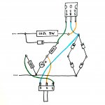
Thanks mcandmar, that Zener is part of the vvr.
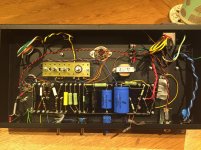
I'm highly suspect of this power transformer. I disconnected everything bar the rectifier and first filter cap and it was still misbehaving. I've checked the diodes and my wiring and everything else I can think of, but basically as soon as there's anything connected to the b+ the PT goes into melt down.
I removed it to start checking Dc resistance etc. and I found continuity between the B+ and the electrostatic shield - which I presume is not at all right. I actually think the whole tranny is completely wired wrong from the factory. Hopefully mouser will take it back!
It lives... sort of.
It works fine at low VVR voltage - sounds good even - but when I turn "up" the VVR (increase the B+) something starts to crap out (my dim bulb gets very bright all of a sudden).
I'm wondering if the first filter cap is damaged from the earlier PT shorts? Anyone any theories?
It works fine at low VVR voltage - sounds good even - but when I turn "up" the VVR (increase the B+) something starts to crap out (my dim bulb gets very bright all of a sudden).
I'm wondering if the first filter cap is damaged from the earlier PT shorts? Anyone any theories?
Thanks djgibson51. Appreciate the help.
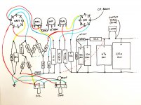
The rest of the layout is now attached. If you can make sense of it I'd welcome your comments.
Is the 6.3v heater winding CT (center tap) connected to B+?
If it were my project, I'd get it working and then add in the VVR later. At this point the VVR would just add to the troubleshooting possibiities, IMO.Stage one. The VVR.
Thanks VictoriaGuy. None of the power transformer CT's are connected.
I think I have it stable now: stupidly, the small cap on the VVR was only rated for 150V. Dunno what I was thinking. Replaced it and the whole circuit is happier. Doing more testing now.
I think I have it stable now: stupidly, the small cap on the VVR was only rated for 150V. Dunno what I was thinking. Replaced it and the whole circuit is happier. Doing more testing now.
The layout diagram shows the 6,3v CT connected to B+ - are you planning to connect this at some point?None of the power transformer CT's are connected.
Isn't the HV CT connected to ground - or am I misreading the full-wave rectifier situation?
That's a mistake on the schematic. As far as I know with a full wave rectifier you *don't* connect the HT CT.
I'd also take his advice and remove the VVR if you can operate safely at the voltage levels you're outputting from the trafo. That's where I am now. I've got my PSU working and delivering power to a circuit that works. Once I get the chassis here completed and everything re-wired I'm planning on then implementing the VVR. Mostly because I'm using the same PSU on a separate project that can run at a much higher voltage.
I'd go so far as to remove the tone stack, NFB, and VVR if you're having issues and get something that outputs sound and is biased correctly. Then when you start adding stuff back in, well....you'll know where you went wrong!
I'd go so far as to remove the tone stack, NFB, and VVR if you're having issues and get something that outputs sound and is biased correctly. Then when you start adding stuff back in, well....you'll know where you went wrong!
I pulled the tubes and the voltages are perfect... output tube toast maybe?
Not necessarily. You've got another tube pulling power there. Plus could be in the heater supply circuit to that tube if you've got something funky going on. try it one tube at a time. Obviously if one of them 'feks everything up and the other doesn't...well then there's the area of your circuit causing issues.
Yea you're right, it's doing it with just the 12ax7 in there.
My finger is pointing at the first filter cap again. It smells funny. *sigh*
My finger is pointing at the first filter cap again. It smells funny. *sigh*
Which schematic are you referring to?That's a mistake on the schematic. As far as I know with a full wave rectifier you *don't* connect the HT CT.
Are you thinking of a bridge rectifier?
All the 'classic' full wave rectifier circuits I see have the HV CT grounded,
Full Wave Rectifier and Bridge Rectifier Theory
https://en.wikipedia.org/wiki/Diode_bridge
https://en.wikipedia.org/wiki/Rectifier#Full-wave_rectification
Sorry - I found your schematic earlier in the discussion. I wasn't really paying attention!
Yes, you have a bridge rectifier, so the HV CT shouldn't be grounded.
And, I missed the voltage divider which you are using to reference your heaters, so that should be fine as well.
Yes, you have a bridge rectifier, so the HV CT shouldn't be grounded.
And, I missed the voltage divider which you are using to reference your heaters, so that should be fine as well.
- Status
- Not open for further replies.
- Home
- Live Sound
- Instruments and Amps
- "Best" Champ / Princeton schematic?