Gotcha. 😀 When J-P asked where THAT noise is being led to I thought he meant some other noise, because THAT noise isn't being led anywhere. 😉
Yeah this comes with old age 🙂
Just did some sketching and I think 2 x ULDO PSU's can be made quite small. This would mean 2 x LT3045 with pass transistors. Using more LT3045 in parallel will make matters expensive and we will already have way better results than SMPS. Besides that we will be using it for digital devices not MC amplifiers. This would mean 2 x 5V 2A (possibly 3A with adequate heatsinks). RF decoupling, common mode filtering, careful tuning of the transformer to avoid unnecessary heat, the whole shebang. Careless souls could use RS15-5 set to 5.5V to feed the board 😉
Of course a new thread will be made if enough people are interested making this happen. "Best low noise 5V compact PSU".
Last edited:
 Eh?
Eh?
Yeah this comes with old age 🙂
Just did some sketching and I think 2 x ULDO PSU's can be made quite small. This would mean 2 x LT3045 with pass transistors. Using more LT3045 in parallel will make matters expensive and we will already have way better results than SMPS. Besides that we will be using it for digital devices not MC amplifiers. This would mean 2 x 5V 2A (possibly 3A with adequate heatsinks). RF decoupling, common mode filtering, careful tuning of the transformer to avoid unnecessary heat, the whole shebang. Careless souls could use RS15-5 set to 5.5V to feed the board 😉
Of course a new thread will be made if enough people are interested making this happen. "Best low noise 5V compact PSU".
Self-correct: that would be 2 x 1.5A with pass transistor or paralleled devices for up to required current.
Hi Jean-Paul,
I'm certainly interested in a low noise 2x PSU. Will there be trimmers to adjust voltage? I need 5V for my Pi and 8V for a new DAC.
I'm certainly interested in a low noise 2x PSU. Will there be trimmers to adjust voltage? I need 5V for my Pi and 8V for a new DAC.
All still open for debate.
Mmmmm.... stepdown SMPS have benefits (and can be built DIY) but the drawback is the need for converting 230V mains voltage to DC. This means either another SMPS in front of it or the classic mains transformer and rectifier/filter cap. Best of both worlds ? We do want low EMI and very low ripple, don't we ?
LT8640S/LT8643S Silent-Switcher-2-Regler - Linear Technology | Mouser Deutschland
Take Advantage of the “Silent Switcher” Architecture | LINEAR TECHNOLOGY | SOS electronic
If step-down SMPS is desirable I think this one would fit the bill exactly:
http://www.analog.com/media/en/technical-documentation/data-sheets/8609sf.pdf?domain=www.linear.com
Last edited:
Hi Jean-Paul,
I'm certainly interested in a low noise 2x PSU. Will there be trimmers to adjust voltage? I need 5V for my Pi and 8V for a new DAC.
Me too. I'm planning how to avoid the ifi iPower SMPS that is currently feeding a Sparky + USBridge in my set-up. The SQ is very very good right now, that's not a problem, although I'd like to get rid of any SMPS in/near my rig.
I'd would be very interested in an one-box optimal solution in this direction. In the worst case my plans were to buy a cheap (although secure/earthed) 3/4 A Chinese LPS for the Sparky and build up myself a PSU ended/based on an LT3045 (500 mA is more than enough for the USBridge) and with, at least, two regulation steps, in order to take advantage of the 0.8μVRMS (10Hz to 100kHz) ripple specs of this LDO.
I remember having seen other regulators with better specs, ripple in the nV region and higher PSRR that those LDO's, but they were much more expensive (3 or 4X) and I don't think they worth it, it would be more an over-engineering for a 'humble' USBridge.
Last edited:
With a swap, a sinosuidal signal that you apply to a given load with and without the PSU connected, and then comparing both measures.
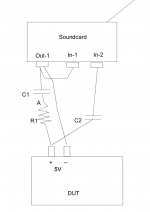
Hook a signal generator (sound card) up to the output of the supply via a blocking cap and series resistor and measure the AC developed across the supply output, do maths.
If you use a stereo sound card or such then by also sampling the drive voltage you can produce a plot of complex impedance not just magnitude, which is far more useful.
Regards, Dan.
If you use a stereo sound card or such then by also sampling the drive voltage you can produce a plot of complex impedance not just magnitude, which is far more useful.
Regards, Dan.
I'm wondering why the load currents being discussed drop by the post.
The SMPS of discussion needs to supply around 3A for the purpose... ...without dropping voltage towards load-max.
Did you have a look at the latest PI3B+ ? Recommendation is 2.5A. The PI itself burns up to 5.7W under load. With a bit of headroom 1.5A I'd consider the minimum. Obviously all add-on devices need to be selfpowered in this case.
I'm also questioning the idea of putting a highest quality LDO to an SMPS. You'd basically put two or more LDOs/DC-DCs in series.
I also have several linear supplies around. No way I'd put them back in.
I'm also questioning the idea of putting a highest quality LDO to an SMPS.
Did you see my measurements?
//
Hook a signal generator (sound card) up to the output of the supply via a blocking cap and series resistor and measure the AC developed across the supply output, do maths.
If you use a stereo sound card or such then by also sampling the drive voltage you can produce a plot of complex impedance not just magnitude, which is far more useful.
Regards, Dan.
Thanks!
What size resistor would you recommend?
//
I'm also questioning the idea of putting a highest quality LDO to an SMPS.
You'd basically put two or more LDOs/DC-DCs in series.
It depends on where the noise is on the SMPS. They all have lots of ultrasonics, I reckon better to have an LC filter (i.e purely passive) before any kind of linear reg. Then, if low noise in the audio band is a requirement, an LDO. Don't feed lots of ultrasonics into a low-noise LDO and expect a crystal-clear mountain stream of power to emerge....
Never overlook it might be common mode. I found linear regulators after an SMPS could be dissapointing. If so the ground and V+ are being modulated in phase.
Like this?
Should probably be a load for the DUT also....
//
I would make the connection to in 1 come from point A via a cap equal to the one on input B, that way you will have close to a pure resistance as one half of the measurement impedance which makes the maths for the down near DC case simpler.
Resistor value depends a lot on the impedance of the network you are measuring (Effectively you are building a low frequency vector network analyser).
As to the load on the supply, sure but remember that that load then becomes part of the one port network you are measuring.
Calibration of such things is done traditionally by measuring with open circuit DUT, short circuit DUT and a known impedance in place of the DUT.
HP/Agilesight have a great publication "The Impedance measurement handbook" that goes into more then you ever wanted to know about this stuff.
Regards, Dan.
- Home
- Amplifiers
- Power Supplies
- Best 5V SMPS ?