Thanks!
In-1 to A via a C... check!
The DUT I suppose will show less than 1 ohm of impedance. Can I make R=20 ohm?
As it seems that the DUT behaves so differently with and w/o load, I need to measure with load as this is the real case anyway.
//
In-1 to A via a C... check!
The DUT I suppose will show less than 1 ohm of impedance. Can I make R=20 ohm?
As it seems that the DUT behaves so differently with and w/o load, I need to measure with load as this is the real case anyway.
//
Last edited:
Can your sound card drive a 20 ohm load, a small power amp might be indicated (Or use the headphone output?).....
Regards, Dan.
Regards, Dan.
Now you just have to write the code, float complex is your friend (or std::complex if you swing that way).
All the measurement is ratiometric and you should be able to generate a complex impedance for each frequency (Hint, for more dynamic range you can apply identical bandpass filters to the reference and measurement channels in the digital domain without changing the result if doing a stepped frequency measurement, no need to have a res bandwidth any larger then you need).
Regards, Dan.
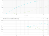
Try measuring the reference channel as well then taking the difference. That way the capacitor in the headphone output will be cancelled out and you should get a straight line for blue.
You should also make a measurement with a short circuit across the DUT connection point, and one with say a 1 ohm resistor in place of the DUT, these three measurements can then be used to calibrate the instrument.
Regards, Dan.
You should also make a measurement with a short circuit across the DUT connection point, and one with say a 1 ohm resistor in place of the DUT, these three measurements can then be used to calibrate the instrument.
Regards, Dan.
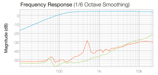
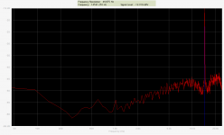
Green: Short instead of DUT
Red: 2r2 instead of DUT
In-2 view.
Both cases has load connected!
Ignore above post!
//
Red: 2r2 instead of DUT
In-2 view.
Both cases has load connected!
Ignore above post!
//
Attachments
Last edited:
Getting tired and doubting mu measurements. Need to eat 🙂
But one correction:
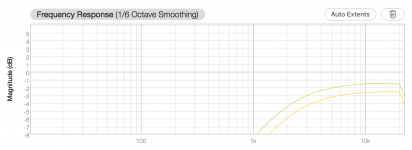
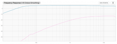
J-P was correct. I did indeed not have a PE. I looked at the outlet today and no PE 8-o. So here new measurements comparing no PE and PE connected.
Still, no diff really...
No PE first, the with PE.
//
But one correction:
J-P was correct. I did indeed not have a PE. I looked at the outlet today and no PE 8-o. So here new measurements comparing no PE and PE connected.
Still, no diff really...
No PE first, the with PE.
//
Attachments

Last edited:
Something odd going on there, with the DUT shorted out you should clearly be seeing just the sound card self noise plus any crosstalk on in2, I would expect a line down around -100dBFs or so!
Of course Ideally your measures would be referenced to In1, but the shorted case should still clearly be WAAAY down in the grass.
A 2.2 ohm resistor with 22 ohms as the source impedance should be giving you a line about 20dB below the In 1 level.
Either that sound card has the crosstalk very much worse then I would expect of this place or something else is very wrong.
Regards, Dan.
I'm wondering why the load currents being discussed drop by the post.
The SMPS of discussion needs to supply around 3A for the purpose...
...without dropping voltage towards load-max.
......
I also have several linear supplies around. No way I'd put them back in.
True 😉. I was thinking out loud and was a bit overenthusiastic. I already see this thread is probably not ending up in result as there are too many wishes. At least that's what I see and I don't want to be dependent on ready built stuff of a category that already gave me many headaches in the past.
You might never use linear PSU's again. OK. I think I see too many advantages using linear PSU's especially with the current ultra low noise ULDO regs. You will never have such results with SMPS in the same price region (probably also not with more expensive stuff 😀). I already use a few centralised DC power stations with very good results and no drawbacks. Mains fed (=green), clean DC power, almost no heat. Did I say NO EMI ?
After thinking and reading datasheets I see no true valid reason at all for using SMPS with such low loads for audio. The devices I built exhibit exemplary behaviour and are a true improvement of the original SMPS they replace. So I continue to go on with realisation of a one board ULDO board with a few outputs. Coincidentally it is an area where DIY still is possible with excellent results.
Last edited:
After thinking and reading datasheets I see no true valid reason at all for using SMPS with such low loads. The devices i built exhibit exemplary behaviour and are a true improvement of the original SMPS they replace. So I continue to go on with realisation of a one board ULDO board with a few outputs.
yes!
It is difficult to do a reasonably efficient universal input linear supply, especially for low voltages (0.95V @ 10A for a modern logic core for example), so SMPSUs have their place.
The trick is to understand the SYSTEM you are designing and to pick the appropriate technology for each part and each rail, and also to use the standard tricks to reduce the influence of switching noise (from whatever source).
I have built widely used mic preamps and processors driven by switchers and the switcher is invisible in the output noise spectrum, it is not even that hard, you just lock the thing in CCM and synchronise to a multiple of the converter sample rate, now any switching spurs alias to a small DC offset that is easy to reject. The faster things (switch ringing) are easy to LC filter away.
For precision analogue, switcher -> LC filter (In the MHz region) -> Modern low noise LDO is generally the way to go, the switcher keeps the LDO dropout voltage down to well under a volt, the LC filter deals with the noise above the area where the LDO has good PSRR and the LDO cleans up the residual, and all for less cost and complexity then mounting the heatsink for a linear (Which will really suffer if you are trying to design for 90 - 265V).
Some play on the RF bench will quickly tell if you have gotten this right.
Regards, Dan.
Anybody have experience with one of these fleabay LT3042 modules?
I am thinking of using one to follow a linear wall wart I have (DC12V out) and adjust down to 8V to feed Abraxalito's LingDAC.
Here is the fancy version with "fever" caps 🙂
I am thinking of using one to follow a linear wall wart I have (DC12V out) and adjust down to 8V to feed Abraxalito's LingDAC.
Here is the fancy version with "fever" caps 🙂
Mosfet switching on Nirvana completely solved . Overshoot and ringing eliminated. Working on the FB network and then we will start taking noise measurements .
- Home
- Amplifiers
- Power Supplies
- Best 5V SMPS ?