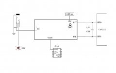
I wouldn't recomend deviations from this schematic. This circuit is the result of extended experimentation. It is the sweet spot for performance and reliability. It should present the lowest possible load to the DUT and make sure what you see is what the amplifier puts out. All that combined with sufficient protection. As said, I haven't tested it with this soundcard but I can verify it works great with CS4272.Looks pretty good. You could improve noise performance furthermore by
reducing input impedance: 10k potentiometer, 2k2 series resistor
Increase gain of first stage a bit
decrease gain of second stage a bit
This mode applies only to the left channel because of room restrictions and requires a TRS on its own for balanced input. So, if you already have done the previous mode you could either leave the right channel on a separate TRS or restore the circuit by putting the electrolytic C35 back in place and have no more access to direct input for this channel. Actually no big deal... For the left channel, remove C34 and take a wire from the negative pad, no return to positive. The on board buffer for the left channel will be permanently stay disconnected. But wiring a TRS like in the schematic allows full functionality for the front panel input and controls just like the previous mode. The new buffer has just a bit higher gain at ~1,25.
Some more things to do on the soundcard board. First remove R26/28/45. These are the output resistors of the on board buffer for the left channel. As said, this part will stay permanently disconnected. There is also a small cap C29 1n near to CS4272. Either replace it with a 2,7n or better solder another 1,5n on top. In any case use C0G caps. From the leads of this cap take wires to #16 and #17 on the pcb which respond to the ADC pins. Finally, another wire from "Vcom" to IC16 pin #1. Pin #1 and #2 are connected providing a convenient pad.
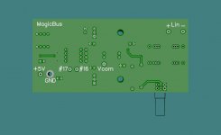
The new pcb should be mounted with a metal 3M 25mm female/female spacer. This will be the ground connection too. 5V should be taken from usb V+. There is a thick trace that connects usb port with L2 and the most convenient point to tap is L2 pad at the bottom side.
That's all! Gerber files uploaded! Volunteers wanted! 🙂
Some more things to do on the soundcard board. First remove R26/28/45. These are the output resistors of the on board buffer for the left channel. As said, this part will stay permanently disconnected. There is also a small cap C29 1n near to CS4272. Either replace it with a 2,7n or better solder another 1,5n on top. In any case use C0G caps. From the leads of this cap take wires to #16 and #17 on the pcb which respond to the ADC pins. Finally, another wire from "Vcom" to IC16 pin #1. Pin #1 and #2 are connected providing a convenient pad.
The new pcb should be mounted with a metal 3M 25mm female/female spacer. This will be the ground connection too. 5V should be taken from usb V+. There is a thick trace that connects usb port with L2 and the most convenient point to tap is L2 pad at the bottom side.
That's all! Gerber files uploaded! Volunteers wanted! 🙂
Attachments

12kHz and 20kHz harmonics start at 24kHz and 40kHz respectively. The humble Behringer will let you have a view up there but there are no tricks to make it competitive at these frequencies! You will need pro equipment for that.
Yes, after all this is an audio interface for music, not an instrumentation/measurement interface.
I am fairly resolved into having to buy another interface at one point. However, using the Behringer, flaws and all, allows me to explore the whole setup and software analysis for really, really cheap. If at worse I need to modify the Behringer itself and I destroy it by a mishap, it won't affect me adversely too much.
Amazing what we can do with cheap audio interfaces nowadays and software.
Last edited:
Thanks for sharing, MagicBus, good job.
Here are some additional suggestions for anyone going that path: I'd suggest injection of a really clean Linear Regulated Power, doing away completely with DC-DC boosters, use two Linear Regs for two different Voltages if necessary, raw coming from mains or batteries if possible.
The other suggestion has to do with the internal DC-DC booster. This sprays interference, so I'd disable it like Remedy did as I mentioned before since your new input card is inside the box, and part of it is right above that interference region. You can also add some shielding for the bottom of your card and in between the original booster and your card if the original booster hasn't been disabled. This may be less effective than fully disabling it though.
You could also host your PCB in a separate box as well, which would provide some additional shielding from the internal booster if that's still operational.
The way you proceeded here is quite cool: keep what is working well in the card, but develop your own mods around it on a separate card and patch it in at judicious places. Keeping the MCU/ADC/USB data lines means we get to keep the Official driver and to the computer and software, this appears as a normal Behringer soundcard but we get the enhancements to go with it.
There could be improvements DAC-side as well with a separate card, or a final implementation on a single PCB.
Last edited:
BTW, this is in line with what I was saying in the case of people doing measurements at 48kHz. Nyquist limits usefulness to half that, so there's not much to base any calculation of harmonic distortion for the higher freqs....12kHz and 20kHz harmonics start at 24kHz and 40kHz respectively.
Ideally, 192kHz would be better for the Behringer, but unfortunately, I see a lot of additional distortion in that mode with my card, so I've decided to stick with 96kHz for now.
However, I will be on the lookout for a card allowing higher bandwidth. It will be worthwhile.
👍 The spirit of this project is that it starts from an inexpensive soundcard that doesn't hurt to loose. First design rule is that all mods should be reversible. Second is to stay handy to use. Third to keep budget low. The on board phantom supply may not be representative of all DC converters so, let's take one step at a time. Same for the DAC section but since you mentioned that, just beefy up a bit those U5/6 output current for a possible next step.😉
Maybe there is a language barrier here, as I wasn't asking for any help. Let me rephrase:
Can you post an ARTA measurement of your mod, just as you did in Post #1 where you showed the before and after?
These new op amps are really good.
Can you post an ARTA measurement of your mod, just as you did in Post #1 where you showed the before and after?
These new op amps are really good.
Understood! The problem is that I don't have this soundcard in working order anymore. The latest mod is cased solely on experience from another project.
Hi all! My name is Alfred Rosenkraenzer, I am a retired analog design engineer. I was happy to work with instruments from Audio Precision in the company. For my home projects I have chosen AudioTester V3.0 SW and a RME Babyface Pro FS USB interface, which is pretty good, but expensive.
For a lab experiment of students I was looking for a cheaper interface. So I found the UMC202HD. Looking for the schematics I found this blog. To be honest, I did not read the whole blog, sorry if I missed something. First of all, thanks a lot to bobon for the schematics.
By playing around with the UMC I got the same problems described in this blog.
1) Spur in the spectrum. It started at 14 KHz moving done to 13.5 KHz over time. Removing L4 in the power supply for the 48 V generator stops it and the spur disappeared. Since I do not need the 48V L4 will stay out.
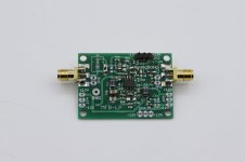
2) The output looks very noisy on a scope. There seems to be no reasonable filter. Looking at the spectrum with an APx555 you see why. I put a 4. Order 21KHz Tschebyscheff Filter on one of my filter boards behind and the output looks nice. I designed a small piggy back board with two filters on to put into the UMC. I will order PCBs soon. In case somebody is interested, just ask. I will also design a PCB with the filter to put behind the UMC in a small alu box.
3) Bad second harmonics when using the 6.35 mm input. The XLR is much better. I think the problem is the CD4066. By replacing it by a 74HC(T)4066 you might get 20 dB better values, but not perfect. I checked both on an evalboard with my RME.
4) Then I did the modifications of the ADC driver and got even a little bit better THD.
Have a look at the pictures attached
Comments welcome!
Alfred
For a lab experiment of students I was looking for a cheaper interface. So I found the UMC202HD. Looking for the schematics I found this blog. To be honest, I did not read the whole blog, sorry if I missed something. First of all, thanks a lot to bobon for the schematics.
By playing around with the UMC I got the same problems described in this blog.
1) Spur in the spectrum. It started at 14 KHz moving done to 13.5 KHz over time. Removing L4 in the power supply for the 48 V generator stops it and the spur disappeared. Since I do not need the 48V L4 will stay out.
2) The output looks very noisy on a scope. There seems to be no reasonable filter. Looking at the spectrum with an APx555 you see why. I put a 4. Order 21KHz Tschebyscheff Filter on one of my filter boards behind and the output looks nice. I designed a small piggy back board with two filters on to put into the UMC. I will order PCBs soon. In case somebody is interested, just ask. I will also design a PCB with the filter to put behind the UMC in a small alu box.
3) Bad second harmonics when using the 6.35 mm input. The XLR is much better. I think the problem is the CD4066. By replacing it by a 74HC(T)4066 you might get 20 dB better values, but not perfect. I checked both on an evalboard with my RME.
4) Then I did the modifications of the ADC driver and got even a little bit better THD.
Have a look at the pictures attached
Comments welcome!
Alfred
Attachments


With my Creative EMU-soundcards I measured remarkable rf-noise with the scope as well. But as I do not want to restrict BW to 20khz there is no filter until now. It may be interesting that this noise never seemed to disturb my measurements.Hi all! My name is Alfred Rosenkraenzer, I am a retired analog design engineer. I was happy to work with instruments from Audio Precision in the company. For my home projects I have chosen AudioTester V3.0 SW and a RME Babyface Pro FS USB interface, which is pretty good, but expensive.
For a lab experiment of students I was looking for a cheaper interface. So I found the UMC202HD. Looking for the schematics I found this blog. To be honest, I did not read the whole blog, sorry if I missed something. First of all, thanks a lot to bobon for the schematics.
By playing around with the UMC I got the same problems described in this blog.
1) Spur in the spectrum. It started at 14 KHz moving done to 13.5 KHz over time. Removing L4 in the power supply for the 48 V generator stops it and the spur disappeared. Since I do not need the 48V L4 will stay out.
2) The output looks very noisy on a scope. There seems to be no reasonable filter. Looking at the spectrum with an APx555 you see why. I put a 4. Order 21KHz Tschebyscheff Filter on one of my filter boards behind and the output looks nice. I designed a small piggy back board with two filters on to put into the UMC. I will order PCBs soon. In case somebody is interested, just ask. I will also design a PCB with the filter to put behind the UMC in a small alu box.
3) Bad second harmonics when using the 6.35 mm input. The XLR is much better. I think the problem is the CD4066. By replacing it by a 74HC(T)4066 you might get 20 dB better values, but not perfect. I checked both on an evalboard with my RME.
4) Then I did the modifications of the ADC driver and got even a little bit better THD.
Have a look at the pictures attached
Comments welcome!
Alfred
Yes, these old CMOS-switches are THD-generators.
Welcome Alfred! Nice to see a pro joining this thread!
Regarding your findings:
1) Indeed I always had the feeling that my "Vcom mod" was a just a band aid fix. Good to see the real culprit was found! A switch can enable phantom power if needed as suggested in a previous post.
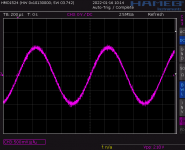
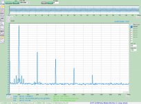
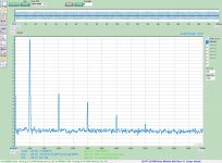
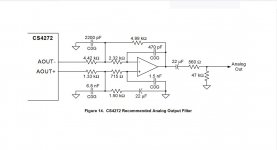
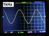
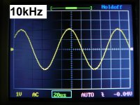
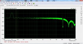
2) Since I'm clueless in designing filters, for my diy soundcard I preferred to follow the schematic suggested by Cirrous Logic on their datasheet - attached for convenience. Also attached screenshots with a small handheld scope that may adds noise on its own. 1kHz and 10kHz sine @ 48kHz sampling rate and 30kHz sine @ 96kHz plus an attempt to see the ultrasonic spectrum of my NOS DAC with that soundcard @ 192kHz.
3) Quite some difference between these IC switches. Thank you very much for this!
Regarding your findings:
1) Indeed I always had the feeling that my "Vcom mod" was a just a band aid fix. Good to see the real culprit was found! A switch can enable phantom power if needed as suggested in a previous post.
2) Since I'm clueless in designing filters, for my diy soundcard I preferred to follow the schematic suggested by Cirrous Logic on their datasheet - attached for convenience. Also attached screenshots with a small handheld scope that may adds noise on its own. 1kHz and 10kHz sine @ 48kHz sampling rate and 30kHz sine @ 96kHz plus an attempt to see the ultrasonic spectrum of my NOS DAC with that soundcard @ 192kHz.
3) Quite some difference between these IC switches. Thank you very much for this!
Attachments

Welcome to the forum Alfred.
Thanks for your investigations and recommendations on this. I just traced this area and removing L4 does disconnect the Booster circuit from Power.
The FFT humps is quite similar to what I scoped too for this area. Good info for the output and filter and the switch too! Every little bit counts.
Thanks for your investigations and recommendations on this. I just traced this area and removing L4 does disconnect the Booster circuit from Power.
The FFT humps is quite similar to what I scoped too for this area. Good info for the output and filter and the switch too! Every little bit counts.
Just as Remedy mentioned and confirmed by Alfred, high-freq spurs are gone. I removed L4.
In white, Before, in blue, After.

In white, Before, in blue, After.
If the soundcard is just for bench type measurements, and only use the TRS input, then it may be worthwhile removing the 4066 and linking across it.
Just bought a ZOOM UAC-2 soundcard. It tested quite disappointing: Works quite restricted on Linux. There seems to be a problem of kernel support. Worse the THD+N figures are far from a bleeding edge. The best I could get was a SINAD about 80dB. I was fooled by a S/N of 120dB which says nothing about THD+N at higher signal levels. Interesting there are no THD or THD+N specs. A glance inside revealed that this product is not intended to be ever repaired or modded. So I looked at the TASCAM US-2X HD. And found out that the specs a slightly inferior to my old EMU-Tracker!
The recent Creative "Soundblaster X-Fi HD Extended" replaces specifying any numbers by vague marketing blabla.
All in all it looks like USB-sound-card are technically on the decline and the only true alternative are the RME - a bit too expensive for me🙁
The recent Creative "Soundblaster X-Fi HD Extended" replaces specifying any numbers by vague marketing blabla.
All in all it looks like USB-sound-card are technically on the decline and the only true alternative are the RME - a bit too expensive for me🙁
- Home
- Design & Build
- Equipment & Tools
- Behringer UMC 202HD for measurements