Audio on linux sometimes is a load of fiddling as well. All you have to do is learn how to set your input and output levels accordingly to what you will measure, not really simple, requiring a steep learning curve. I recommend all settings scaled in dBFS instead of dBV or dBU- no need for a calibration at all.I don't see any problem with your soundcard. As it comes from the factory, the best it can do is what you post, I think. The raised noise floor is because the enormous input gain. The same explains the sensitivity to environment conditions. Could you repeat with all gain controls -input/output- completely turned down?
Regarding this high frequency peak, it seems it's not consistent in all specimens. In mine, it was shown much lower within the audio spectrum. Having it already above 20kHz I suggest you should ignore it since this soundcard is actually meant for viewing audio only.
Agreed! However, full scale -well -3dB- is necessary to reveal the ghosts lying under the carpet. This was a design priority in my other soundcard project which is a joy to use. I think it's feasible with this one too. Be warned it's for hardcore adventurers though... Stay tuned!
After a "small" modification at my AUT ("Amp Under Test") my measurements turned out to be quite disappointing: H3 had increased from previous -100dB to -80dB. It took some headscratching to find the culprits: The two 330pF phase compensation caps that I had replaced were SMD0805 X7R MLCCs. These distorted due to their well known non-linear behaviour. Replacing them by NPO-types fixed the problem and gave the expected result.
All in all the measuring setup did its job🙂
All in all the measuring setup did its job🙂
I don't see any problem with your soundcard. As it comes from the factory, the best it can do is what you post, I think. ... Could you repeat with all gain controls -input/output- completely turned down?
Regarding this high frequency peak, it seems it's not consistent in all specimens. In mine, it was shown much lower within the audio spectrum. Having it already above 20kHz I suggest you should ignore it since this soundcard is actually meant for viewing audio only.
Here's Output Gain approximately as before around 2 o'clock and Input Gain zeroed. My dynamic range is lower. NB: I haven't done any calibration in ARTA.
And here's both Input Gain and Output Gain zeroed:
If you meant that the default audio interface results look not far from that first one, similar to your first graph in this thread, I can see similarities.
The other difference with mine is the seemingly sample-rate related spike at around 26kHz.
Can't guarantee that my card is from the factory per se because I bought it at least second-hand from a guitarist. I don't know if he is the first owner or if he dabbled with opening it, but I do remember opening it once myself. Technically, I haven't changed anything inside the card.
There is flux residue underneath the PCB so a cleanup would be good.
Last edited:
Today I was called to a customer who had an annoying noise problem around his home studio that made it impossible to do any recording. He told me on the phone that it was worse with single coil p.u. and the expensive mains filter could not fix the problem at all. I assumed a magnetic field interference caused by some loop in the electric installation. So I soldered a small inductor to a guitar cable, plugged this into my tiny battery amp and set to max gain. With this "sniffer" we checked the cellar and finally landed in the garden where the noise was all around. It turned out there was an electric power loop around the garden and the noise source was the pond pump. Removing it from mains solved the problem. Talking more about this I learned the noise problem has been around for about 2 yrs - since the installation of the pump.
Resuming this is a quick and dirty work-around and next summer the problem with the pump has to be fixed. Nonetheless the customer is happy now being able to proceed with recordings.
Resuming this is a quick and dirty work-around and next summer the problem with the pump has to be fixed. Nonetheless the customer is happy now being able to proceed with recordings.
There seems to be some misunderstanding: Setup input gain to minimum, but no, do not set output level to minimum but close to max. Do a loopback from ouput connected with input. Increase output level until best THD readout is obtained. Should be somwhere between -10 ~ -2dBFS of output.
Your plot shows a 1kHz input level of -60dB - far too low, no wonder that a poor THD results.
As a starter set generator level to -6dBFS and do a loopback test
Your plot shows a 1kHz input level of -60dB - far too low, no wonder that a poor THD results.
As a starter set generator level to -6dBFS and do a loopback test
Last edited:
Everything you see is loopback....set output level to ... max. Do a loopback from ouput connected with input.
Do you mean 'Increase input level' here?Increase output level until best THD readout is obtained. Should be somwhere between -10 ~ -2dBFS of output.
I did something like that initially with no averaging, and hence I could monitor THD as well as harmonics visually near-realtime after resetting at each position, at -6dBFS as R.E.W. suggests.
Your plot shows a 1kHz input level of -60dB - far too low, no wonder that a poor THD results.
Correct. Even R.E.W. warns you about the low threshold when you attempt to calibrate the audio interface at that level.
Here's a new test, Input Gain zeroed and Output at around 1 o'clock. There's a spot in this region around 1 - 2 o'clock where the THD will jump from 0.0xx% to 0.1xx% or 0.2xx% abruptly:
Not sure I calibrated Volts properly: only got a non-True RMS DVM, so I must probably revisit and multiply by a factor in R.E.W.
Yes, occurs when REW does not find the 1kHz fundamental i think.Does anyone else get missing Distortion numbers under the graphs like I do here?
Increasing input gain to adjust level is definitely the wrong way when ouput level is too low.
You have to increase the output level instead. Do not use headphone output but line-out.
I do not know your soundcard. With mine I do not set output level with an analogue potentiometer
but by REW-software: "Set generator level" -> xyzdBFs.
I do not have a clue what you are doing. Where does the signal run?
What is your generator level set to in REW?
And my crystal ball sticks in the service center😕
What is your generator level set to in REW?
And my crystal ball sticks in the service center😕
Indeed, there are too many parameters to follow here. Please have another round with all this but with sampling rate set at 48kHz. CS4272 has the typical noise shaping that keeps THD+N low only up to ~50kHz. If you set the sampling rate higher than 48kHz then the average THD+N is ruined.
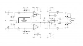
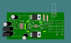
So, the UMC202 checks OK at least for usb microcontroller/drivers and audio codec. Let's give it a chance! I'm not going to test this. I'm giving it for everyone who wishes to try. It's a small pcb made to fit inside the chassis like the one shown in the first pic. It is based on the input stage of my diy soundcard that proved stable and indestructible for more than two years I've been using it so far. It bypasses all circuitry in front of the ADC and provides a new input, high impedance, true differential floating with attenuator and overvoltage protection, ready to accept an amplifier.
Some comments on the parts. There are a few smd but they are manageable with an ordinary soldering iron. Do not use different opamps. Resistors should be low ppm - I used 50ppm- and small caps should be C0G. Input caps at 1μF/400V may be a bit optimistic since there is not much room for these. Then again, 100V should be sufficient protection. Anyway, go for the biggest you can fit. Electrolytics C9/10/11 are 100μF. R1/R2 are the current limiters. Admittedly, plane resistors are not the preferable option. You could improvise using other schemes like back to back mosfets or something. What I used is incandescent lamps. Finally, the psu takes 5V from the usb post and boosts to +/-12V. U5/U6 are the DC converters. I don't provide a specific part number because the global shortage might make it difficult to source. But there are quite a few that would do. Search for SIP-4 11,5*6mm, 5V in, single 12V out no less than 50mA. These do not feed the opamps directly. If you wish to do so, then use 9V DC converters as higher might stress the OPA1632 in this application. But I thought to provide for linear regs U3/U4 for additional filtration. Starting from LM7809/7909 to whatever out there is made as a replacement to them, like LT3042/94 which is what I used.
There will be another post with details for the transplantation. 🙂
Attachments

Indeed, there are too many parameters to follow here. Please have another round with all this but with sampling rate set at 48kHz. CS4272 has the typical noise shaping that keeps THD+N low only up to ~50kHz. If you set the sampling rate higher than 48kHz then the average THD+N is ruined.
The THD does increase with the higher rates, but too low and the THD for a high freq. signal will have less meaning. Keeping things at 96kHz seems a good compromise to me. I can always switch back to lower rates, but then THD for even a 12kHz signal doesn't have much data for the calculation to rely on, let alone for a sig at 20kHz.
True differential, really cool. I'd say especially cool if Remedy's True Phantom Off is also used with it.
Looks pretty good. You could improve noise performance furthermore bySo, the UMC202 checks OK at least for usb microcontroller/drivers and audio codec. Let's give it a chance! I'm not going to test this. I'm giving it for everyone who wishes to try. It's a small pcb made to fit inside the chassis like the one shown in the first pic. It is based on the input stage of my diy soundcard that proved stable and indestructible for more than two years I've been using it so far. It bypasses all circuitry in front of the ADC and provides a new input, high impedance, true differential floating with attenuator and overvoltage protection, ready to accept an amplifier.
Some comments on the parts. There are a few smd but they are manageable with an ordinary soldering iron. Do not use different opamps. Resistors should be low ppm - I used 50ppm- and small caps should be C0G. Input caps at 1μF/400V may be a bit optimistic since there is not much room for these. Then again, 100V should be sufficient protection. Anyway, go for the biggest you can fit. Electrolytics C9/10/11 are 100μF. R1/R2 are the current limiters. Admittedly, plane resistors are not the preferable option. You could improvise using other schemes like back to back mosfets or something. What I used is incandescent lamps. Finally, the psu takes 5V from the usb post and boosts to +/-12V. U5/U6 are the DC converters. I don't provide a specific part number because the global shortage might make it difficult to source. But there are quite a few that would do. Search for SIP-4 11,5*6mm, 5V in, single 12V out no less than 50mA. These do not feed the opamps directly. If you wish to do so, then use 9V DC converters as higher might stress the OPA1632 in this application. But I thought to provide for linear regs U3/U4 for additional filtration. Starting from LM7809/7909 to whatever out there is made as a replacement to them, like LT3042/94 which is what I used.
There will be another post with details for the transplantation. 🙂
reducing input impedance: 10k potentiometer, 2k2 series resistor
Increase gain of first stage a bit
decrease gain of second stage a bit
12kHz and 20kHz harmonics start at 24kHz and 40kHz respectively. The humble Behringer will let you have a view up there but there are no tricks to make it competitive at these frequencies! You will need pro equipment for that.The THD does increase with the higher rates, but too low and the THD for a high freq. signal will have less meaning. Keeping things at 96kHz seems a good compromise to me. I can always switch back to lower rates, but then THD for even a 12kHz signal doesn't have much data for the calculation to rely on, let alone for a sig at 20kHz.
- Home
- Design & Build
- Equipment & Tools
- Behringer UMC 202HD for measurements