I will try to formulate the question more specifically 🙂 but in short it will not work.
I'm not learned enough to determine where the truth is, and where the fairy tales. In the specifications for some audio opamps says about a certain optimal signal levels range couple with minimal distortion. My etalon DAC is placed in other location now and I cant check my theory..
Now the question: Can such distortions occur due to the fact that too loud signal in amplitude is fed to the inputs of ad8694? In first for DAC output.
PS. hat off to the you attempt! this looks hopeful.
I'm not a specialist myself too. All I can say is that specifications for signal level with low distortion are also a function of power supply rails. So, here we have not enough power supply voltage to amplify the necessary signal to drive the ADC with low distortion. In other words yes, too loud signal is fed to the opamp compared to its Vdd. Besides that, distortion depends on impedance matching.
In the specifications for some audio opamps says about a certain optimal signal levels range couple with minimal distortion.
Are you refering to the total noise+distortion graphs against amplitude. These measure noise+distortion, not distortion, relative to the signal level (not absolute). For a very low distortion amp the noise usually dominates till the signal is several volts in amplitude, but that's not because the noise is high, just that the distortion is ultra-low.
You could measure the actual distortion at lower amplitudes by statistical averaging (to reduce the noise), and it is likely consistent with the values at higher amplitudes, or lower. Things get more linear with smaller signals typically.
Hi everybody! I need your collective help.
The datasheet for XMOS says "If required a 3V3 oscillator can be used (for example when sharing an oscillator with other parts of the design), but a resistor bridge must be included to reduce the XI/CLK input from 3V3 to 1V8."
I do not clearly understand what is meant by "resistor bridge"?
Is that Voltage divider across two resistors or one series resistor that looks like a "bridge" between source and destination?
And also a very restricted description for sc2200 chip. Will it start with 1V8 in case using the XMOS as master clock?
It looks like only a practical experiment will give the answer...
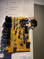
So i did the direct-in mod. And nothing else for now.
The loopback THD+N is the best i ever got now (0.0021%)
The pin configuration on the in and outputs are as this :
Jack is connection for Direct in ::
Direct in : RCA ---> Jack T = (+) / Left
Direct in : RCA ---> Jack R = (GND) / Right (Gnd when used unbalanced)
Direct in : RCA ---> Jack S = (GND)
Jack is connection for out ::
Out : Jack T ---> RCA (+)
Out : Jack R ---> RCA (GND)
Out : Jack S ---> RCA (GND)
But i keep getting the nasty 50Hz noise, as soon as i do a real measurement on one of my amps. (Pre. + Power Amps)
I find it fun and exciting to see the THD figures through, and maybee i just have to accept the noise line voltage the Behringer with cables are picking up.
I disconnect my laptop from mains, and put it away from my desk along with the Behringer during measuring.
I guess it's the signalcable's picking up the noise or maybe the USB connection.
Will continue to hunt it down tomorrow. -😉
Jesper.
Attachments

Very nice Jesper! Some comments: The soundcard loop measurement shows odd order harmonics possibly because of clipping. Please do not force it to reach 0dBFS, it simply cannot do it... The rest of my mods were to take it as closer as possible. Plus taming a nasty high frequency peak, not present to all specimens, apparently yours too.👍 Regarding 50Hz noise, I can't think of anything else than a ground loop issue. Given the way it works with this direct input mode, you will need either to lift DUT from ground or isolate it from the soundcard actively or with a transformer. For starters you could try to disconnect ground from one of the interconnects, maybe the one that goes to the soundcard input.
In any case please keep in mind that the direct input is completely unprotected against overvoltage, and this would be just 2,5V. Consider to add diode clamps, something that I didn't do myself.
In any case please keep in mind that the direct input is completely unprotected against overvoltage, and this would be just 2,5V. Consider to add diode clamps, something that I didn't do myself.
If the DUT allows hum/noise voltage to develop between its 'signal in' gnd and 'signal out' gnd terminals, and the soundcard has its signal in and out gnds connected, then there is likely to be noise/hum loop signals imposed on the measurement. Such hum/noise can be suppressed by modifying the DUT, or as indicated by disconnecting a gnd on one of the interconnects (or including a low resistance - eg. 10 ohm).
Although my EMU0404 includes a metalized plastic enclosure, I sit the soundcard in a large aluminium 'BBQ tray' and electrically clip the tray to the input signal gnd, and sometimes put another inverted tray over the top. Measures such as this, plus using a laptop, and experimenting with layout and what nearby mains powered devices are switched on, are often the sort of comparisons and effort needed to suppress hum signals from a measurement plot for a DIY setup. Sometimes there is also a need to reduce any processing load on the PC/laptop, especially any processes that include USB or sound related activity.
Although my EMU0404 includes a metalized plastic enclosure, I sit the soundcard in a large aluminium 'BBQ tray' and electrically clip the tray to the input signal gnd, and sometimes put another inverted tray over the top. Measures such as this, plus using a laptop, and experimenting with layout and what nearby mains powered devices are switched on, are often the sort of comparisons and effort needed to suppress hum signals from a measurement plot for a DIY setup. Sometimes there is also a need to reduce any processing load on the PC/laptop, especially any processes that include USB or sound related activity.
If you get issues with coupling like that, the best solution I can think of would be to capacitively couple the grounds and add a high value resistor; given that the grounds can be separated between in and out (if the chip provides its own isolation or diff.) Not always possible. The other one is pure galvanic isolation but that's sub-ideal.
1N5221B or similar zener should be able to clamp this if you are willing to live with the reduced headroom (not being able to push as close to zero.)In any case please keep in mind that the direct input is completely unprotected against overvoltage, and this would be just 2,5V. Consider to add diode clamps, something that I didn't do myself.
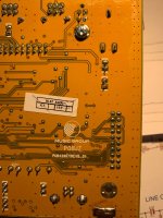
This is correct.If you remove the circled parts it won't work. Even if its a CMOS part it helps to reduce the distortion of the impedances are matched on the +/- inputs in a noninverting setup like this. They also may ne necessary for stability. I'm sure they were not added to put more parts in the product, considering how cost sensitive this manufacturer is.
Hello and glad to see all the input's here on my "issue"...
I tried today the following thing's ::
Created a cellphone external battery supply, and powered the Behringer with this.
Laptop USB data+ -----> Behringer
Laptop USB data- ------> Behringer
Laptop USB (GND) ----> Behringer
Laptop USB + //
Batterypack + -----------> Behringer
Batterypack (GND) ----> Behringer
It actually did a noticable difference, giving a slightly better THD+N with both Normal-input, and Direct-input that is.
When sitting on my desktop with every nearby 50Hz mains powered off, i have no 50Hz showing with Normal-input. With direct-input there is around 30dB 50Hz spike (100, 150, 200Hz etc... also)
This is the same with or without GND connected at the loopback input.
Loopback THD+N is not good (~0.25%) with Normal-input, but very good at Direct-input (0.0021%) around -30dB. But there are many odd harmonics now, also the famous 8kHz spike appears now Magicbus ;-) - At Normal-input i have only 2nd ,3nd harmonics but again a bad THD+N
Okay... let's measure some real amp's now ::
Test is done batterypowered Behringer & Laptop.
I have 3 poweramp's, loaded with 8Ohm, tested without GND connection on the soundcard input.
The result's are more or less the same as with GND connected, telling me again that this Behringer is way to sensitive and picky.
So this lead me to the conclusion that i simply cannot trust the reading, except that i can see if 2nd, or 3nd harmonics are dominated, and also i can see how much the THD+N on my different amp's are (More or less THD+N)... but i'am sure the number's aren't the right one's.
I also like to see how much LEFT & RIGHT channel are balanced in the same setup.
Regarding the hum(50Hz + friends), i allways turn volume way up and put my ear close to my 91+dB speaker (no noise, no hum)...
Jesper.
I don't recall mine being so sensitive to emissive environment... The box although plastic has this metalized coating. The noisier normal input may hide the 50Hz peak under the floor and only appears with the direct input that allows to look deeper. The power supply mod you did does not interrupt gnd connection to PC. Just some thoughts... Except for a loop test, I always used mine together with an interface when measuring amps. Perhaps it made the difference.
Keep in mind that the pure 50Hz fundamental is hard to hear due to human hearing capabilities (Fletcher Munson curves). What you perceive als 50Hz noise are the harmonics above - and their amplitude decays rapidly versus frequency. Your test equipment is much more sensitive than the ears.Regarding the hum(50Hz + friends), i allways turn volume way up and put my ear close to my 91+dB speaker (no noise, no hum)...
Jesper.
This is the Pete Millet's interface your'e used Magic ?Except for a loop test, I always used mine together with an interface when measuring amps. Perhaps it made the difference.
(Perhap's i need to travel to Greece for a quick checkout 😎)
Anyway i will look for some linetrafo to see if i can isolate the connection, just to see ;-)
Jesper.
Yep...Your test equipment is much more sensitive than the ears.
I will keep this in mind.
Jesper.
Yes, that's what I used, and you are welcome! 🙂This is the Pete Millet's interface your'e used Magic ?
(Perhap's i need to travel to Greece for a quick checkout 😎)
Anyway i will look for some linetrafo to see if i can isolate the connection, just to see ;-)
Jesper.
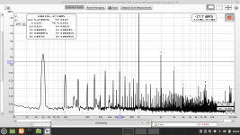
Attached a FFT of a tube amp using this compo.
Attachments
Forget any line-trafos when measuring distortion - they are distorting from most tiny levels 😡This is the Pete Millet's interface your'e used Magic ?
(Perhap's i need to travel to Greece for a quick checkout 😎)
Anyway i will look for some linetrafo to see if i can isolate the connection, just to see ;-)
Jesper.
Okay...Forget any line-trafos when measuring distortion - they are distorting from most tiny levels 😡
I also looked for some useable, which i do not have in stock, so i will give it up, thank's for the warning.
Jesper.
Okay... ;-) -And thank's for the invite to Athen's... 😎Yes, that's what I used, and you are welcome! 🙂
Attached a FFT of a tube amp using this compo.
Nice spectrum. The last i took with my AlephJ scaleddown AlephMimi is at same -17dB level, but spikes are much higher, and THD+N higher, but but but not so far away from your'e measurement anyway...
I will dig into the galvanic/isolation/etc... on audio signals and let's see if i will figure it out eventually.
Maybe i will try some other cables (we have some coax for intercom at work i can use) within the next day's ?
Last day for me now on Xmas vacation it is...
Jesper.
Attachments

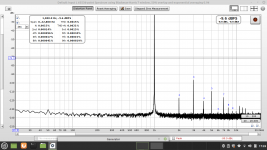
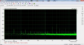
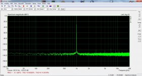
A small tutorial -mostly thoughts- from a non expert, put to your judgement. The following graphs have been captured with another soundcard, the one linked in post #120 but I think they are conclusive.
First is the soundcard loop for reference. The second is a tube amp with 50Hz and 100Hz plus their intermodulation byproducts. I assume that this is what the amp is delivering and the soundcard just reads. The third is an LM3886 amp - namely Rod Elliots "workbench amp" with one stage filter psu. 100Hz ripple and its harmonics. There is also a 50Hz peak but not interacting with the rest, so I think this is not an amp's product but induced in the soundcard's input probably from interconnects or something. The last one is Salas DCG3 with its ripple free psu and magnetically shielded toroids so the small 50Hz peak again should be picked after its output. I hope it helps...
First is the soundcard loop for reference. The second is a tube amp with 50Hz and 100Hz plus their intermodulation byproducts. I assume that this is what the amp is delivering and the soundcard just reads. The third is an LM3886 amp - namely Rod Elliots "workbench amp" with one stage filter psu. 100Hz ripple and its harmonics. There is also a 50Hz peak but not interacting with the rest, so I think this is not an amp's product but induced in the soundcard's input probably from interconnects or something. The last one is Salas DCG3 with its ripple free psu and magnetically shielded toroids so the small 50Hz peak again should be picked after its output. I hope it helps...
Attachments


If this is all getting down to the point interconnects are an issue I'd recommend getting a second box that is the size of the interface, and just having an IO box. Run cables into there, and then you can use other connectors that avoid that stuff, plus more shielding as you can shield very tightly.
- Home
- Design & Build
- Equipment & Tools
- Behringer UMC 202HD for measurements