
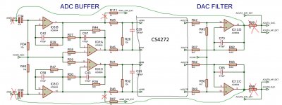
A complete schematic of the sound card? Very nice! For the part I've reversed engineered, it seems accurate. Thanks!
IMHO the board is implemented with bugs - different VCOMs are used in one path. And mic & line mixer also with stranges. Need to think about it at my leisure ..
My finding too. Either circuitry blocks were designed by different teams or it's an attempt to make reverse engineer difficult, especially in the usb microcontroller section. OTOH we must appreciate that they made it work with usb 5V, no internal DC boosters. Those CMOS opamps are top class but very fragile so they had to add things to protect them.
Maybe someone will come in handy ... Working model in the simulator. All pF of small-sized capacitors do not correspond to reality. Possibly errors, I hastily drew ..
marked parts are redundant and increase the noise.
Attachments

If you remove the circled parts it won't work. Even if its a CMOS part it helps to reduce the distortion of the impedances are matched on the +/- inputs in a noninverting setup like this. They also may ne necessary for stability. I'm sure they were not added to put more parts in the product, considering how cost sensitive this manufacturer is.
AD8691 is unity-gain stable opamp just short the output to n-input like IC9, also, I see no any sign of the input impedance matching in these redundant parts. To me it looks like Chinese engineering as is because the distortions of that ADC 40-50db higher than the effect you mentioned. Look, they even didn't calculate poles/zeros, everywhere 470pF sometimes with 10k, 15k, or 680ohms - 100% nonsense. BTW, R38/R39 are useless for the same reason, rather increase noise that's it.
PS: if resistors R29/R44 would be tied to the C29 directly, that definitely makes sense and quite common for ADC buffers.
PS: if resistors R29/R44 would be tied to the C29 directly, that definitely makes sense and quite common for ADC buffers.
Last edited:
IVX I wrote above - 470pF are default values. I did not unsolder caps to measure actual capacitance.
AD8691 is unity-gain stable opamp just short the output to n-input like IC9, also, I see no any sign of the input impedance matching in these redundant parts. To me it looks like Chinese engineering as is because the distortions of that ADC 40-50db higher than the effect you mentioned. Look, they even didn't calculate poles/zeros, everywhere 470pF sometimes with 10k, 15k, or 680ohms - 100% nonsense. BTW, R38/R39 are useless for the same reason, rather increase noise that's it.
PS: if resistors R29/R44 would be tied to the C29 directly, that definitely makes sense and quite common for ADC buffers.
Half of this thread was about a catastrophic failure after removing parts that didn't make sense in first sight.
If you remove the circled parts it won't work. Even if its a CMOS part it helps to reduce the distortion of the impedances are matched on the +/- inputs in a noninverting setup like this. They also may be necessary for stability. I'm sure they were not added to put more parts in the product, considering how cost sensitive this manufacturer is.
When I removed the 1k in series/10k shunt between the buffer and the ADC, the opamp delivered the spirit... Generally opamps driving capacitive load need to self gain margin accordingly. It's all explained in previous posts. The particular opamp is very sensitive to that.
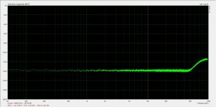
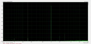
it is ADC itself has such noise floor because its noseshaper has a loop gain roll-off at 40-50kHz. The top Cirrus ADC has the same roll-off, AKM's ADCs a bit higher, ESS up to 200kHz almost flat noise floor.
all things are here XCore Exchange - Index page datasheet isn't a key but sample code is the big deal.
The microcontroller should be this one https://www.google.com/url?sa=t&rct=j&q=&esrc=s&source=web&cd=&cad=rja&uact=8&ved=2ahUKEwj7yayCmJryAhXKyaQKHbd2CgIQFnoECAQQAw&url=https%3A%2F%2Fwww.xmos.ai%2Fdownload%2FXS1-U8A-64-FB96-Datasheet(1.8).pdf&usg=AOvVaw0p7p-uvOiwQYwGihMkg9cd I've checked pin compatibility. There are also a flash memory chip and a clock generator that I couldn't identify. Especially the clock doesn't seem to be pin compatible with other msop-10 clocks. Go figure!
Thanx, XMOS is very similar ..
My idea is try to use one XTAL for both XMOS and 10-pin chip.
I found that the difference of spread between the 24 MHz resonators is noisy in the sound range, like a +48v generator.
My idea is try to use one XTAL for both XMOS and 10-pin chip.
I found that the difference of spread between the 24 MHz resonators is noisy in the sound range, like a +48v generator.
MagicBus Do I understand correctly that high %THD occurs at the input of OpAmp but not at the output?
I cut off all unnecessary connections and turned the loop from output to input (as in the picture). The maximum rms levels are approximately the same in about 1v. Proteus shows the maximum signal level at the input before clipping is also 1v. I think it makes sense to play with the gains in the simulator. I will try do it at next week.
I cut off all unnecessary connections and turned the loop from output to input (as in the picture). The maximum rms levels are approximately the same in about 1v. Proteus shows the maximum signal level at the input before clipping is also 1v. I think it makes sense to play with the gains in the simulator. I will try do it at next week.
Attachments
Not sure if I understand your question. The input and output buffers are pretty much standard designs with low distortion at least theoretically. But this doesn't mean they match the requirements of the audio codec chip. And you should also keep in mind that Vdd is ~4,75V after some filtering on the usb Vbus. So if you have a look at the CS4272 datasheet, you will see that the input buffer should have a bit more headroom to drive tha ADC at full scale plus it should provide the lowest possible output impedance for low distortion but this opamp wouldn't make it against the ADC input capacitor.
Additionally regarding the output stage, the datasheet gives an example that compensates for the audio codec output phase difference.
Perhaps you would like to have a look here for my attempt to overcome all of this.
DIY soundcard intended for measuring amplifiers
Perhaps you would like to have a look here for my attempt to overcome all of this.
DIY soundcard intended for measuring amplifiers
- Home
- Design & Build
- Equipment & Tools
- Behringer UMC 202HD for measurements