Hi here...
It's been a while, project is going slowly forward 🙂
I'm trying to design a card to plug into the SuperRanger.
The card is able to keep the output/target voltage within the limit of the modded Behringer.
The target voltage is ofcause userchangeable in software.
(- Actually the -0dB ---> -42dB are also level changeable so that other and greater target's can be chosen, but this is not the idea for me that is.)
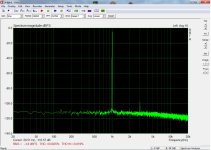
I took a sweep of it with my sinegenerator through an toroidal trafo witch gains the output from the sinegen. from 7Vrms to around 59Vrms. (~180Vpp)
There is a little glitch at startup, but it's caused by the software controlling the bodeplot (SineGen. + Oscilloscope modded python script)
As can be seen on the sweep, the output is not like other autorangers, witch typically puts the output in a greater range(s).
But the whole idea here is to create something witch fits exactly the modded Behringer. (-4dBFS ---> -1dBFS or so)
Happy newyear!
Jesper.


It's been a while, project is going slowly forward 🙂
I'm trying to design a card to plug into the SuperRanger.
The card is able to keep the output/target voltage within the limit of the modded Behringer.
The target voltage is ofcause userchangeable in software.
(- Actually the -0dB ---> -42dB are also level changeable so that other and greater target's can be chosen, but this is not the idea for me that is.)
I took a sweep of it with my sinegenerator through an toroidal trafo witch gains the output from the sinegen. from 7Vrms to around 59Vrms. (~180Vpp)
There is a little glitch at startup, but it's caused by the software controlling the bodeplot (SineGen. + Oscilloscope modded python script)
As can be seen on the sweep, the output is not like other autorangers, witch typically puts the output in a greater range(s).
But the whole idea here is to create something witch fits exactly the modded Behringer. (-4dBFS ---> -1dBFS or so)
Happy newyear!
Jesper.

Here are a few more shoot's.
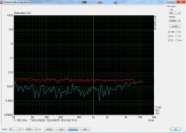
The bodeplot is without the trafo, so sweep is from 1Vpp to 19Vpp
The two FFT's are just to show on the Behringer that the target is at the range where I wanted it to be for the setup to show.
(I can't remember what the target was set to in the SuperRanger at the two FFT's, but I guess it was 1050mV?)
EDIT:: Don't mind the messy and grassy FFT, it's taken directly on the protoboard shown in previously post
Jesper.
Great project, Jesper! Keep up the good work!
For my Audio Analyzer project, I played with the idea of using an auto-ranger but opted for fixed gain settings for the sake of simplicity and getting the project finished sooner. I now use crappy Aliexpress rotary switches, but seriously considered replacing them with relays. But after applying contact spray, they seem to be stable now. At least for as long as it will last... But using relays would mean a complete overhaul of what I already made, so I left the idea in the drawer for future work if I were to do it all. But if I were to do an overhaul, then I might as well include your auto-ranger as well. Are you planning on designing a PCB for it?
Anyway, I already did a search for suitable relays, and the Omron G5V that you use was one of my preferred models as it had the lowest contact resistance of the models I researched. I don't know your relay contact lifetime expectancy, but there are other models that are supposed to have a longer lifetime. I assume the auto-ranger will do quite some relay switching, so this might be something to take into consideration. But perhaps in practice, this is just an academic issue. No criticism is intended here; don't get me wrong. It's just a matter of choice, maybe. At least for manual switching, the G5V lifetime would be more than adequate, and the lower contact resistance of the Standard version would make me opt for this one. Below is the list of relays I researched.

This list will be on my website-still-in-the making (working on it for two years already now... 😱😕). As a sneak preview, I attached pdf outputs of three of the web pages. One about the Mic Preamp, one about the stepped attenuator + Line-Input amplifier and the last one with an overview of some key performance data. Maybe you find it interesting.
Jan
For my Audio Analyzer project, I played with the idea of using an auto-ranger but opted for fixed gain settings for the sake of simplicity and getting the project finished sooner. I now use crappy Aliexpress rotary switches, but seriously considered replacing them with relays. But after applying contact spray, they seem to be stable now. At least for as long as it will last... But using relays would mean a complete overhaul of what I already made, so I left the idea in the drawer for future work if I were to do it all. But if I were to do an overhaul, then I might as well include your auto-ranger as well. Are you planning on designing a PCB for it?
Anyway, I already did a search for suitable relays, and the Omron G5V that you use was one of my preferred models as it had the lowest contact resistance of the models I researched. I don't know your relay contact lifetime expectancy, but there are other models that are supposed to have a longer lifetime. I assume the auto-ranger will do quite some relay switching, so this might be something to take into consideration. But perhaps in practice, this is just an academic issue. No criticism is intended here; don't get me wrong. It's just a matter of choice, maybe. At least for manual switching, the G5V lifetime would be more than adequate, and the lower contact resistance of the Standard version would make me opt for this one. Below is the list of relays I researched.
This list will be on my website-still-in-the making (working on it for two years already now... 😱😕). As a sneak preview, I attached pdf outputs of three of the web pages. One about the Mic Preamp, one about the stepped attenuator + Line-Input amplifier and the last one with an overview of some key performance data. Maybe you find it interesting.
Jan
Attachments
Oops, my bad... It seems I have missed many posts since my last post in October. I was not informed by diyAudio of any new posts submitted until today.
In the previous post, I shared some pages from my website. I have two more pages I'd like to share as well: the introduction page of the Analyzer project and another one describing the UMC202HD mods I did. Although, for now, I'm satisfied with the UMC202HD performance, that doesn't mean there isn't room for improvement. E.g. the OPA1632 ADC frontend proposed in this thread could provide even better noise and distortion performance. And I could have improved low-pass filtering on the DAC output to get rid of the noise-shaping noise outside the audio band.
But as I already said, I'll leave the Analyzer untouched for the time being and will just use it for what it was meant for: measuring microphones and other audio circuitry.
Jan
Attachments
Hi Jan....
Seems I have to do some reading here 🙂
Allway's nice when you post something here, and thank's for the kind words.
Main reason I use the omron's I do, is that I thought I was better off, having some "bigger" relay's for the attenuator part of my project, so I bought a bunch of them.
I'm not sure if you read all the post where I introduced my ranger from here. (https://www.diyaudio.com/community/threads/behringer-umc-202hd-for-measurements.341309/post-7474195)...
eventually I nailed the last bit of unwanted noise.
The stuff I'm prototyping right now is the "output" card, which are supposed to be piggybacked into the SuperRanger motherboard.
My plan is to have pcb's made for the "output" card, and when fully loaded and tested, I will proberly redo the motherboard, as there are something I would like to change.
I have the gerber's for the motherboard only, and I have two spare pcb's on hand from production.
Jesper.
I attached the attenuatorpart / motherboard schematic here. The outputcard is more or like a "copy" of the AMB's Alpha24 Here! ... I need to write to them, before I will post it here; guess it's not a problem as it seems to be an opensource project there.
Hi Jesper,
Thank you too. Glad to hear that you appreciate my contributions! I have only supeficially scanned all the posts since my last read of October. Will read more in detail later.
Interesting designs from The Valve Wizard site and that Alpha24 output stage. Should be a good choice.
To all: Enjoy New Years Eve, wishing you all the best for next year and see you then!
Jan
Hi all,
Question: did anyone of you build or just consider an external Codec board with the CS4272? I mean, use the UMC202HD only as a digital interface and have all the analog stuff including the CS4272 on an external PCBA. You would no longer need to do the cumbersome modifications of the crappy analog circuitry on the UMC202HD board and make something really good right away.
Jan
I tried a UMC202 with REW but found the performance to be terrible. In fact I returned it, saying I believed it to be faulty.
I also tried two other similar audio interfaces with similar disappointments.
Instead I use a UCA222 which does not have any controls, input Z of 27K, output Z of 400r, max in and out level of 2dbv (1.26v RMS)
Attached is a screenshot from yesterday of my NAD 326BEE's preamp section.
If I need to measure more than 1V I have a simple -20db passive attenuator.
My only issue is that due to the 20kHz bandwidth square wave testing is misleading. I use a Picoscope for this.
We all know the UMC202HD is far from ideal without any serious modifications. That's what much of this thread is about. And I think we have all proven that, with the right modifications, it can actually perform quite well. You can get very close to the performance specs from the CS4272 datasheet. But I fail to see how a cheap UCA222 can be a better choice. Assuming your second plot is a loop-back test, I see (T)HD figures much higher compared to even an unmodified UMC202HD. Can you explain to us why you disliked the UMC202HD so much and why you think the UCA222 is a better choice, price aside?
And yes, soundcards should not be used to measure square waves having harmonics beyond the audio bandwidth, though an UMC202HD at 192 kHz sample rate should perform better than a UCA222, which is limited to 48 kHz sample rate.
Jan
And yes, soundcards should not be used to measure square waves having harmonics beyond the audio bandwidth, though an UMC202HD at 192 kHz sample rate should perform better than a UCA222, which is limited to 48 kHz sample rate.
Jan
None of the screenshots are loopback, both are the output from the NAD326BEE's preamp.
Using the UCA222 avoids the need for input and output amplifiers.
I tried all those other interfaces and couldn't achieve low distortion on loopback tests and the dynamic range seemed limited.
I am sure they could be improved with external circuitry but for my use, 1v input and output from the UCA and with an optional passive attenuator for amplfier testing works for me.
For the cost of just ~$25 I recommend trying one, depending on what you want to measure.


Here are loop measurements for UCA202, the older version but apparently very similar to UCA222. The audio codec in mine is the Coolaudio V2902. In the later models was replaced by PCM2902. Mind you these measurements are with input/output buffers bypassed i.e. the audio codec directly connected to the buffers of Pete Millett's PC interface.
Attachments

Hi,Hi all,
Question: did anyone of you build or just consider an external Codec board with the CS4272? I mean, use the UMC202HD only as a digital interface and have all the analog stuff including the CS4272 on an external PCBA. You would no longer need to do the cumbersome modifications of the crappy analog circuitry on the UMC202HD board and make something really good right away.
Jan
I think this is close to what you ask. But instead of using the Behringer's usb interface, I used another Xmos module.
https://www.diyaudio.com/community/...-for-measuring-amplifiers.363385/post-6421403
The UAC222 does have the same Coolaudio V2902 ADC/DAC which is probably the same as the PCM2902.Here are loop measurements for UCA202, the older version but apparently very similar to UCA222. The audio codec in mine is the Coolaudio V2902. In the later models was replaced by PCM2902. Mind you these measurements are with input/output buffers bypassed i.e. the audio codec directly connected to the buffers of Pete Millett's PC interface.
Nothing wrong with those results either.
I have bought an IK Multimedia iRig HD2 96kHz interfacefrom Amazon to compare. (using the UAC222 as the output)
It's a mono interface so does also have an output and uses 32bit A/D, D/A. Will find out today if it will function with REW.
Last edited:
Thank you, MagicBus! I have only read some of the posts. I'll read the rest later. I'd like to have an interface where I can set the sampling rate etc. via the ASIO drivers, as with the UMC202HD. It seems yours is manually controlled, but I haven't read all yet. Anyway, inspiring and I will read the rest of the posts later.Hi,
I think this is close to what you ask. But instead of using the Behringer's usb interface, I used another Xmos module.
https://www.diyaudio.com/community/...-for-measuring-amplifiers.363385/post-6421403
Jan
OK, so if my understanding is right, then the usefulness of an Audio Interface for your purpose is determined by the maximum output level? Agreed, the UMC202HD with just 0.98V RMS output level @ 0 dBFs is less than the 1.26 V from the UCA and is too low for many applications. And if you want to reduce the THD of the UMC202HD to a more useful level, you'll even have to set the output level a few dBFs lower and reduce the level to, say, 0.8V. But a low output level is easily fixed by an external, single Op-Amp amplifier with 5X amplification and powered by two 9V batteries. Then you'll get an even more usable output range, and you'll be able to test the NAD amp up to its specified input level of 2V or more.None of the screenshots are loopback, both are the output from the NAD326BEE's preamp.
Using the UCA222 avoids the need for input and output amplifiers.
I tried all those other interfaces and couldn't achieve low distortion on loopback tests and the dynamic range seemed limited.
I am sure they could be improved with external circuitry but for my use, 1v input and output from the UCA and with an optional passive attenuator for amplfier testing works for me.
For the cost of just ~$25 I recommend trying one, depending on what you want to measure.
From the NAD amp FFT plot and the UCA loop-back FFT plot you shared, I fail to see how the UCA can be a useful instrument to measure the NAD THD performance, as the THDs are in the same order of magnitude (NAD @ 0.004%, UCA loop-back 0.0031%). You could try the REW harmonic cancellation feature to polish up the fidelity of your measurements, though. Or you could add a notch filter to the input as described in this thread to get rid of the fundamental frequency in the FFT and prevent distortion introduced by the sound card. On top of this, I would consider the SNR of a little over 70 dB, that I calculated from the loop-back plot to be far from adequate.
A comparison between the UCA222, UMC202HD and a laptop soundcard was made here on Audio Science Review: https://www.audiosciencereview.com/...eview-and-measurements-behringer-uca222.2036/
Conclusion: If you're on a budget, you're probably better off using the laptop soundcard rather than a UCA222. Except maybe if the max output level of the laptop soundcard is too low.
Cheers, Jan
Hi JanIn the previous post, I shared some pages from my website.
When shall we see your full document with the modifications?
The extract shows it is very well written and illustrated

George
Thank you George! Nice to hear that my work is appreciated. That really motivates me to finish the remaining chapters as soon as possible! There'll be 15 chapters in total. The most important and most labor intensive 6 chapters are finished now. I hope I will be able to finish all of them by the end of February. But I'm a slow writer, so no guarantees. I may share an intermediate update in a week or two.
Cheers, Jan
Cheers, Jan
- Home
- Design & Build
- Equipment & Tools
- Behringer UMC 202HD for measurements