Cool enough... this will guide me for a start.
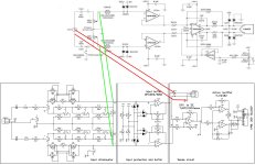
I measure now, directly with an 221ohm resistor in series at output (U3) at Att+ (pin 1 at the AttOut plug)
I will also try to measure after the Diff. to SE. opamp (U5)
Both opamps are OPA1656. The protection diodes are BAV199 (D3, D5, D7, D8)
The bypass PSU capacitors on the opamps are them here Link!
I will dig into this for the next day's, great help 👍
Does your software allow averaging? That will give a clue whether it is noise or periodic fix harmonics
Hello...
@dddac I assume you mean the FFT software which is REW, and yes it have provision for averaging.
I will look into this, thank's.
I did not yet try to analyze the opamp with my scope, but will for sure do, just need to read some more regarding this.
Anyway I soldered the C4 and C5 into place with an 33pF COG 50V, but it did not change anything, at least not at 1kHz which is the only freq. I tried as for now.

Jesper.
@dddac I assume you mean the FFT software which is REW, and yes it have provision for averaging.
I will look into this, thank's.
I did not yet try to analyze the opamp with my scope, but will for sure do, just need to read some more regarding this.
Anyway I soldered the C4 and C5 into place with an 33pF COG 50V, but it did not change anything, at least not at 1kHz which is the only freq. I tried as for now.
Jesper.
So I found the issue now.
I tried with the oscilloscope, and I did catch something, but I had no clue what to do.
As I still belive that I connected the opamp's the correct way, except that I ofcause cannot verify the pcb layout as I am no proff.
Well... :
It's the ESP32 which are making the FFT grass/noise.
I figured it out by disconnecting it when the circuit was powered on, and I could clearly see that the FFT was much cleaner then.
Fortunately it's possible to by the opensource nature, changing everything 🙂 ... So I started out disable wifi and stuff.
But the real change was when I slowed down the CPU speed from 240MHz.
There are still thing's to try, like CPU sleep modes and stuff; but long story short, setting it to around 40MHz cured most of the FFT grass.
In meantime I changed the OPA1656 into the OPA1612. The OPA1612 is less prone to the 50Hz mains sipp--->through here in DK at least.
Jesper.


Edit : I will try to notch it also, to see the real world THD numbers instead of the Behringers limit.
Jesper
I tried with the oscilloscope, and I did catch something, but I had no clue what to do.
As I still belive that I connected the opamp's the correct way, except that I ofcause cannot verify the pcb layout as I am no proff.
Well... :
It's the ESP32 which are making the FFT grass/noise.
I figured it out by disconnecting it when the circuit was powered on, and I could clearly see that the FFT was much cleaner then.
Fortunately it's possible to by the opensource nature, changing everything 🙂 ... So I started out disable wifi and stuff.
But the real change was when I slowed down the CPU speed from 240MHz.
There are still thing's to try, like CPU sleep modes and stuff; but long story short, setting it to around 40MHz cured most of the FFT grass.
In meantime I changed the OPA1656 into the OPA1612. The OPA1612 is less prone to the 50Hz mains sipp--->through here in DK at least.
Jesper.
Edit : I will try to notch it also, to see the real world THD numbers instead of the Behringers limit.
Jesper
Last edited:

Hi, hope you are all well...
While waiting for a powersupply PCB to sit on topback of the "motherboard", I thought I would share some pictures of the build progress 🙂
The powersupply is just two DC-DC switchers (-15/+15 & -12/+12) to create with some plain linear regulator's (I also attached a little picture of it here)
Well let's see how it goes when it's finish and inserted...
It's still in development everything including the code, but I like when I have the chance to box it all up, seeing how it would work in real world.
And it's still not a autoranger as I had none piggyback card yet, not even started that progress out yet 😉
I've tamed the ESP higi'sh speed processor, getting it down to 10MHz when attenuator code and in/out voltage has stabilised during voltage input adjustment, or when powered up... Same goes when using the setup menu's, then the processor will run at fullspeed so everything seems responsive and fast.
I tried a lot of different stuff, also setting the processor at "deep sleep", but for now it does not seem to do any change. The real change is when CPU is brought down to 10MHz, then nearly all fluctractions are gone, as I did show in my previous post here (that was at 40MHz through).
Another thing, which also cleans the FFT a bit up, is that I can run it with "floating" in/out, choosing wheter or not connecting -IN to GND, this seem's to do a great change to the whole setup...
(One of the day's i will change the processor speed at my input card in my (@Salas) DCG3 preamp., I remember i did have some forrest of noise deep down the -dB's when I measured it last year... I belive it would be cleaned a lot up as the processor there also runs at 240MHz which is not really usefull for in/out and some display).
In the code I made some menu's, where to choose different setup's, could be in/out configuration, attenuator adjustment (where the switching between the -dB step's occur) and so on, there is (allmost) no limit here... But I won't even consider my code to be in alpha state yet 🙂, but it's working fine that is.
That's it, actually no more than a few pictures...
Jesper.
Hi here and hope you have a good sunday out there?
I finally got my PSU board installed into the SuperRanger, and took some measurement.
The measurement shown are all "floating" and with battery powered SuperRanger.
Still it's not an autoranger, just an attenuator 🙂
I'm satisfied with the result's i got.
And yes I know, I maybe post to many pictures, but here are the final one's diy-attenuator only, with it's own PSU buildin.
Btw. I did test the attenuator with voltages up to around 70vac. This is done by connecting my JDS6600 generator into the sec. of an 6v torridal transformer, taking the output of at the primary side. It's stable and it's working fine.
[Scope screenshoot is @ -12dB]
Jesper.
Testing the thing with my notchfilter
I'm not sure why there are introduced spikes starting from excatly 82.5Hz when running through my SuperRanger ---> Notch ?
Also I see that there are some 2nd. harmonic introduced through SuperRanger. I did allready try all cablecombinations etc... nothing seem's to cure the 82.5Hz + friends through.
That said, I proberly don't wan't to care much about it, as I would newer test any DAC or whatever superlow THD equipment, other than directly into the notch + Behringer anyway 😉
Jesper.
82,5Hz might be the difference or the sum of two higher harmonics projecting to the lower range. Who knows, actually who cares? You can use the soundcard+notch filter for low level signal and add the SuperRanger to test a power amp that most likely will have much higher noise to mask this tiny interference.
Yes @MagicBus ... Thank's for reminding me, what it's intended for 🙂
Quick test with my beloved and much used CloneAmp@workshop shows that it's the same as expected THD number's when tested with or without my SuperRanger between... Not the best meassureable amp. but good enough for my shop/room!
EDIT :: The noisefloor is like 10dB lower when SR is at -12dB compared to directly into Behringer and the "skirt" is also "smaller" as expected.
[8ohm loaded at 3.83vac = ~1.9watt]
Jesper.
Here through SR @ -12dB

And here directly into Behringer.

Quick test with my beloved and much used CloneAmp@workshop shows that it's the same as expected THD number's when tested with or without my SuperRanger between... Not the best meassureable amp. but good enough for my shop/room!
EDIT :: The noisefloor is like 10dB lower when SR is at -12dB compared to directly into Behringer and the "skirt" is also "smaller" as expected.
[8ohm loaded at 3.83vac = ~1.9watt]
Jesper.
Here through SR @ -12dB
And here directly into Behringer.
Last edited:
One thing I would really like to try some day based on your schematic in post #653:
The input attenuator section wired directly in place of the soundcard's potentiometer, omit the protection and buffer section -it's already built in the soundcard- omit the diff to SE section and take signal from one OPA1656 -from inside the soundcard- to the active rectifier. Or the other way around, keep your circuit down to the buffer output and connect this to the OPA1632 inside the soundcard.
The input attenuator section wired directly in place of the soundcard's potentiometer, omit the protection and buffer section -it's already built in the soundcard- omit the diff to SE section and take signal from one OPA1656 -from inside the soundcard- to the active rectifier. Or the other way around, keep your circuit down to the buffer output and connect this to the OPA1632 inside the soundcard.
Dc/dc converter modules, presumably like the RECOM ones you are using, would typically need an LC filter on input and output rails to avoid internal switching signal from splaying out to nearby low signal circuitry. The LC values depend on the converter - the original Newport units have an app note with suggested LC values. That may be related to your signal artifacts.
Hi...
When looking back, I should have used the same protection circuit as you did in the balanced input board (resistor/ancient lamp + BAV199 diode-clamp's), but still with the option to disable it with relay K5 as shown on schm. in post #653, I would then get better THD number's when protection circuit is "enabled".
The idea to use the internal balanced board circuit to "feed" the SR is also very good, but I prefer a standalone unit for now, but maybe you mean otherwise?
The best thing i discovered yesterday, is that voltage in and out can be seen on the display, not needing to make measurement's with an external DMM for REW calibration and readout, that's a nice feature.
Also the phenomomen with the 82.5Hz, 165Hz. etc... only occours when my active notch is in place.
I'm not done testing this yet, I will try if putting an LPF at around 100kHz in the chain to see if it's some switching noise bleeding through when (and only when) the notch is in use... I also have the possibility to test it with a linear psu I got, this would proberly also tell me if the 82.5Hz and friend's are PSU related or circuit related?
Thank's for all the advice here 👍
Jesper.
I actually had the idea' when I started the journey, to replace the potmeter (100k) with precision voltage divider's (at Behringer input) to see if I could get even better result's.One thing I would really like to try some day based on your schematic in post #653:
The input attenuator section wired directly in place of the soundcard's potentiometer, omit the protection and buffer section -it's already built in the soundcard- omit the diff to SE section and take signal from one OPA1656 -from inside the soundcard- to the active rectifier. Or the other way around, keep your circuit down to the buffer output and connect this to the OPA1632 inside the soundcard.
When looking back, I should have used the same protection circuit as you did in the balanced input board (resistor/ancient lamp + BAV199 diode-clamp's), but still with the option to disable it with relay K5 as shown on schm. in post #653, I would then get better THD number's when protection circuit is "enabled".
The idea to use the internal balanced board circuit to "feed" the SR is also very good, but I prefer a standalone unit for now, but maybe you mean otherwise?
The best thing i discovered yesterday, is that voltage in and out can be seen on the display, not needing to make measurement's with an external DMM for REW calibration and readout, that's a nice feature.
I had some of them DCDC switchers, where the datasheet gave some uH values for coils, but the two I use (+15/-15 & +12/-12) don't mention anything about that in the datasheet, just the max capacitance on the output.Dc/dc converter modules, presumably like the RECOM ones you are using, would typically need an LC filter on input and output rails to avoid internal switching signal from splaying out to nearby low signal circuitry. The LC values depend on the converter - the original Newport units have an app note with suggested LC values. That may be related to your signal artifacts.
Also the phenomomen with the 82.5Hz, 165Hz. etc... only occours when my active notch is in place.
I'm not done testing this yet, I will try if putting an LPF at around 100kHz in the chain to see if it's some switching noise bleeding through when (and only when) the notch is in use... I also have the possibility to test it with a linear psu I got, this would proberly also tell me if the 82.5Hz and friend's are PSU related or circuit related?
Thank's for all the advice here 👍
Jesper.
I agree, for a stand alone unit you need the extra stage. I was just worrying about too many SE buffers in a row. Have you by any chance measured the output of only one phase of the SR -say positive and ground- connected to the soundcard's input?
Hello MB...
There are the input buffer right after the attenuator resistor/relay string's, and right now I measure directly at the AttOut, located at the top of the sense circuit part.
The input buffer is one OPA1612 that's it.
The Diff. to SE is only "stealing" the signal and converting it to SE for the active rectifier.
I'm not sure if I'm right, but I don't think the diff. to SE part will affect the signal?! -That's what I believe at least 🙂
Jesper.

I agree, for a stand alone unit you need the extra stage. I was just worrying about too many SE buffers in a row. Have you by any chance measured the output of only one phase of the SR -say positive and ground- connected to the soundcard's input?
There are the input buffer right after the attenuator resistor/relay string's, and right now I measure directly at the AttOut, located at the top of the sense circuit part.
The input buffer is one OPA1612 that's it.
The Diff. to SE is only "stealing" the signal and converting it to SE for the active rectifier.
I'm not sure if I'm right, but I don't think the diff. to SE part will affect the signal?! -That's what I believe at least 🙂
Jesper.
Hi Jesper,
I understand. What I mean is to keep your circuit as is and take output only from AttOut+ and ground -SE- and feed the soundcard diff input. Just to see if the soundcard's CMRR is affected. Not sure if it's going to make any difference though.
I understand. What I mean is to keep your circuit as is and take output only from AttOut+ and ground -SE- and feed the soundcard diff input. Just to see if the soundcard's CMRR is affected. Not sure if it's going to make any difference though.
🙂 It's the laungauge barrier which at least are tricking me...I understand. What I mean is to keep your circuit as is and take output only from AttOut+ and ground -SE- and feed the soundcard diff input. Just to see if the soundcard's CMRR is affected. Not sure if it's going to make any difference though.
It's clear now, that it should/could be interesting to see how it would measure when your'e input circuit is bypassed.
I'm using T/R and not S at input now, just as it was intended to btw...
Jesper.
- Home
- Design & Build
- Equipment & Tools
- Behringer UMC 202HD for measurements