Hi...
Yep got it 👍
Did you redesign the original circuit for the Behringer input balanced board?
I see that there are some minor changes, and an extra opamp added, compared to the one I use.
I attached the schematic I use below this new invention 🙂
Jesper.


Yep got it 👍
Did you redesign the original circuit for the Behringer input balanced board?
I see that there are some minor changes, and an extra opamp added, compared to the one I use.
I attached the schematic I use below this new invention 🙂
Jesper.

Cool...
One more thing.
I opened up my Behringer today cause I had to change the switch which on/off's the Jackplugs GND into the Behringer.
Well at the same time I soldered a wire onto C2 where you have a switch which connects -in to ground. Does this diff. to SE works as expected? This could save me a lot of cables. I mean I could then use normally TRS balanced cables for all configurations instead of having both floating and normal cables.
Hope I'm clear here
Jesper...
In my soundcard I've installed a BNC input connector, center to positive, outer to negative. Interconnects are built with coaxial, core to center, shield to outer BNC for RCA at the other end, or twisted, hot to center, cold to outer BNC for XLR at the other end. This way I can connect SE and balanced DUT leaving the soundcard input floating all the time. It works great in 99% of the cases. It is rare that the C2 ground switch is needed.
Assuming your TRS input connects T to positive, R to negative and S to ground, you have a similar input configuration. If you wire the other end of your interconnects to TS -mono- positive phase to T, negative to S, or the same way to RCA or XLR -in all cases ground from the soundcard not connected- then you don't need this input GND switch. You could rewire it to C2 to keep it as an option.
A schematic may follow later. 🙂
Attachments
-
 D8A2F0F9-E6ED-4C0A-9E32-A3DD1036238C_1_105_c.jpeg255.3 KB · Views: 227
 -
 3FD6F2C2-E556-4CC9-847C-A0AEB799653F_1_105_c.jpeg264.4 KB · Views: 248
 -
 4DDFC138-A7CE-4EE1-BDE7-EB99FD787683_1_105_c.jpeg298.1 KB · Views: 220
 -
 6853C9FD-D1CD-42DF-A3C3-70645307D6A9_1_105_c.jpeg223.6 KB · Views: 190
 -
 1A7F85FA-D7E4-4DD6-8EEF-9FBDBB730FCE_1_105_c.jpeg104.8 KB · Views: 204
Noise = 1n/SQR*Hz instrumentation amplifier differential input and output. Please look at that:
https://thatcorp.com/that-1580-low-noise-differential-audio-preamplifier-ic/
Can single IC replace the entire preamp schematic? to lykkedk
https://thatcorp.com/that-1580-low-noise-differential-audio-preamplifier-ic/
Can single IC replace the entire preamp schematic? to lykkedk
Attachments
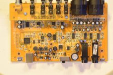
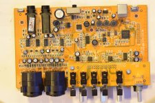
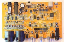
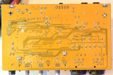
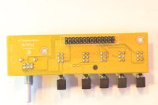
https://photos.app.goo.gl/h9oWecKhrFKtxgMV7Very high resolution photos of
Behringer UMC 202HD PBBs
The pictures in full resolution (.jpg) can be downloaded from Google Photos. That is because diyAudio site compress the files especially for ca. 10MB files.
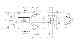
A typical INA with very low input impedance for the reason that high CMRR requires tight tolerances not easy to do at high impedance. One INA that I found with high input impedance and CMRR extending to MHz is AD8130 but the penalty is noise. The OPA1632 itself has an impressive loop THD+N but is useless as a front end in this application because it can hardly take a 10k attenuator. That's why the SE input buffers are needed.Noise = 1n/SQR*Hz instrumentation amplifier differential input and output. Please look at that:
https://thatcorp.com/that-1580-low-noise-differential-audio-preamplifier-ic/
Can single IC replace the entire preamp schematic? to lykkedk
Thanks,
I realise now THAT IC has 0.0003% distortions vs OPA1632 ultra low distortion 0.000028%. The current noise is small at JFETS but voltage noise is there 100 K potentiometer and 33K resistors on the JFETs inputs makes more noise than the OPAMS. Can the attenuator be after the impedance buffers OPA1656 at very low resistance?
I realise now THAT IC has 0.0003% distortions vs OPA1632 ultra low distortion 0.000028%. The current noise is small at JFETS but voltage noise is there 100 K potentiometer and 33K resistors on the JFETs inputs makes more noise than the OPAMS. Can the attenuator be after the impedance buffers OPA1656 at very low resistance?
The attenuator and the in series resistors at the input are an evil necessity. Without them the OPA1656 will be exposed to potentially harmful voltage and the soundcard would be good only to measure low level signal. For measuring a power amp, an external attenuator would be needed, and this takes us back to the starting point. A solution would be to put the input protection out of the way with a switch when is not needed but this requires user's precaution. Or Jesper's SuperRanger. 🙂
I like the incandescent light bulb solution low resistance in normal operation and high resistance at over-voltage. A genius solution! There are some schematics that extend the voltage range of OPAMPs.
https://www.analog.com/media/en/tec...e-input-voltage-range-of-standard-op-amps.pdf
https://www.ti.com/lit/an/sboa510/s...28298&ref_url=https%3A%2F%2Fwww.google.com%2F
There are 100K resistors but on the output of the OPAMP and the noise is short-circuited by OPAMP output(Z=0). Perhaps that can help for tube amp project measurements. For me is godt to have an upgrade to my interface as it is. Thank to all of your contributions. It looks like going out from the Datasheet of ADC/DAC coder was a bad choice from the original designers. Perhaps they try to be better safe than to be sorry. Also price and complexity concerns.
Thanks! I don't know how this scheme works. Worth to try sometime.
Engineers do miracles given the rules they have to obey...
Engineers do miracles given the rules they have to obey...

Please check for stability. I had bad experience messing with these resistors. It's described in the earlier part of this thread starting from post #48.
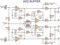
I am going to re-root the line-in button direct to the ADC buffer inputs from the input jack. Also change the input impedance (resistors) of the ADC buffer from 10K to 50K-60K to work also with my guitar that have 2K ohms coils.WIMA 1uF PP capacitors on the inputs of ADC buffer.
I removed and short-circuited two the restores from the positive inputs of the OPAMP. There is no need for them MOSFET_OPAMP 5fA input current induces negligible offsets at unitary gains. Change the value resistors from 1k to 68 ohms. 1n capacitors remains the same.
I removed and short-circuited two the restores from the positive inputs of the OPAMP. There is no need for them MOSFET_OPAMP 5fA input current induces negligible offsets at unitary gains. Change the value resistors from 1k to 68 ohms. 1n capacitors remains the same.
Attachments
It is very stabile because I did not change the original schematic. Is the same on the outputs.
They used 1k for mixing the signal with direct monitoring that use also 1k resistors can be much lower perhaps 40 ohms but I do not want to try that.
on the inputs I also intend to put blue or UV LED(2,7V-3,2V) diodes in parallel and opposite polarity for protections zener 4,2V diodes also may be the think. The diodes connected to the power rails do not work because 0.6V instead 0.3V max datasheet sheet specifications.
- Home
- Design & Build
- Equipment & Tools
- Behringer UMC 202HD for measurements