Hi Dan,
Can not wait the sequel! Compiled those parts, but still miss the 27K feedback resistor. Can I substitute with 20k, 22k? or 33k?
Is there any "Design guide" for LM1875 like the one for LM3886?
Can not wait the sequel! Compiled those parts, but still miss the 27K feedback resistor. Can I substitute with 20k, 22k? or 33k?
Is there any "Design guide" for LM1875 like the one for LM3886?
That is the one I'll try.The actual "middle of the road" transformer selection corresponds to these transformers, with their 18-0-18 vac.
Edits said:Hi Dan,
Can not wait the sequel! Compiled those parts, but still miss the 27K feedback resistor. Can I substitute. . .
There are many designs possible. This thread is about just one design, which does include a 27k resistor. Feel free to use the PM/Email feature!
The resistor values that I've used are widely available in "variety packs" from retail storefront electronics hobby shops.
Heatsink.
I had a knife out, scoring some plain veroboard so that it would snap to appropriate sizes, got curious and unpacked the box with the new heatsinks. . .
WOW!! OMG! That heatsink (above) just arrived in the mail. Its whopping huge! Some metric versus U.S. conversion error? Anyway, about half that large will do it.
Its so tall that I'll need to go to the hardware store and buy a metal cutting blade to fit my "Junior Sabre Saw" (we call that a JigSaw, here in the U.S.). Although that's quite inexpensive, if you do it, use a dust mask and eye protection.
You can also get heatsinks from these guys: http://www.apexjr.com/Sinks.htm
At "established" (old) computer shops, you can find good-size "Slot CPU" type heatsinks, probably for free. You can also find suitable heatsinks inside defunct equipment that's sold at "thrift" stores and second-hand stores, also at little to no cost.
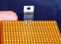
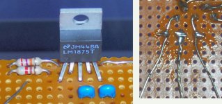
This photo shows the pin spacing. Its a view from the bottom side of the board. Note that this is plain phenolic board, without any copper on it.
There's at least 1/8" of pin sticking through the board. And there's plenty of room to get a hook or loop of copper wire around any of the pins, without worries about any connections too close to any other.
See photo.
(click photos to enlarge)
There's at least 1/8" of pin sticking through the board. And there's plenty of room to get a hook or loop of copper wire around any of the pins, without worries about any connections too close to any other.
See photo.
(click photos to enlarge)
Attachments
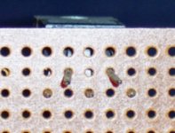
Next step, we get some nice 24ga or 22ga copper wire (or copper core wire) and do like this picture.
These 3 wires are about an inch longer than the edge of the board. Each has a small hook so it can make solid contact with the LM1875's pins.
These little hooks are dipped into the flux jar before soldering. That makes for instant success with the soldering.
Make the end of your soldering iron, bright, silver, clean, by wiping it with either a wet sponge or #0000 steel wool. That helps to make the connections nice and clean.
Attachments

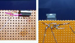
Okay, here's our 27k feedback resistor.
That's its name because its one of the two resistors that make up the NFB. That stands for Negative Feedback Loop, and it sets your gain.
This 27k resistor is red, purple, orange.
After setting the resistor in place (as shown), I looped it around the pin of the LM1875 (as shown).
Because the connection is smaller than my fingers, I used Hemostats, although needle-nose pliers will do in a pinch. 😀
Then I painted the area with flux (for success).
Lastly, I cleaned the tip of the iron and soldered.
I'm proud of this picture. 😉 Click on it.
Attachments
Before we get much further, I need to say:
The design on this thread, and its schematic, are free for diy, non-profit use.
Okay!
Next, we'll hook up the speaker + wire. And, that step completes the connections to the chip.
The design on this thread, and its schematic, are free for diy, non-profit use.
Okay!
Next, we'll hook up the speaker + wire. And, that step completes the connections to the chip.
Attachments
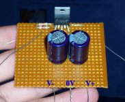
Its time to hook up the main ground lead.
This is thicker than any other wire.
The first of the power caps help hold the ground lead in place.
They're 100nF, which is 0.1uF, and they probably have the number "104" written on them.
You can use the plain 3 cent ceramic caps or something that looks prettier. See photo.
To hook up caps on veroboard, just hold your wire firmly against the pin/leg of the capacitor. Bend the pin/leg of the capacitor over the wire (it holds the wire). Apply flux, and solder into place.
Attachments
It wasn't talent. It was tools.
See these two posts:
http://www.diyaudio.com/forums/showthread.php?postid=1509701#post1509701
http://www.diyaudio.com/forums/showthread.php?postid=1509879#post1509879
See these two posts:
http://www.diyaudio.com/forums/showthread.php?postid=1509701#post1509701
http://www.diyaudio.com/forums/showthread.php?postid=1509879#post1509879
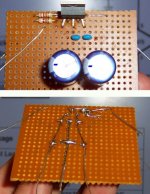
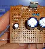
Its time to attach the onboard power capacitors.
Notice the orientation in the photo below.
You can use 470uF or 330uF.
A 50v model is recommended.
See that the centerpoint between the two power caps does connect to the ground (0v) lead.
Notice the orientation in the photo below.
You can use 470uF or 330uF.
A 50v model is recommended.
See that the centerpoint between the two power caps does connect to the ground (0v) lead.
Attachments
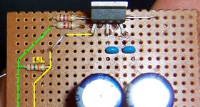
Its time to do the input circuit! Whee! 😉
The first, and most important part of the input circuit, is the 15k input impedance resistor.
This one is brown, green, orange.
It runs from the input + to the 0v (ground), thereby presenting a load.
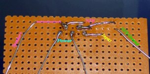
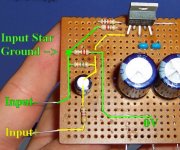
Now, in the photo below, the "input star ground" has started to form. Have a look at the photo below and see that the NFB and the input will ground at the same point (marked in green).
The first, and most important part of the input circuit, is the 15k input impedance resistor.
This one is brown, green, orange.
It runs from the input + to the 0v (ground), thereby presenting a load.
Now, in the photo below, the "input star ground" has started to form. Have a look at the photo below and see that the NFB and the input will ground at the same point (marked in green).
Attachments
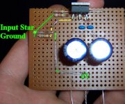
The following photo will show the hookup from Power ground to Input ground.
Compare this with the photo above. We have added just the one wire to make this connection.
This will complete the "input star ground" See photo--its marked in green.
EDIT: Notice that only one end of the 15k resistor connects to ground. The other end (marked yellow in the photo) is your signal + line.
Attachments
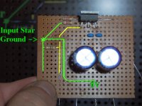
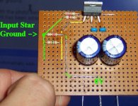
Optional Component
This post is about an optional component called the "groundlift" resistor. It can be from 2.2 ohm to 8 ohms.
What it does it to make your input circuit "less attractive to hums" because a bit of added resistance prevents, "point of least resistance."
Compare the photo above with the photo below.
Notice the optional component has been added--the groundlift resistor.
This one is 2.2R (2.2 ohms) and its red, red, gold, as shown.
Attachments
Hey, let's add our input filter cap and its compensation resistor.
The input filter cap blocks DC from entering the amplifier.
This particular input filter cap, I spec'd for 2.2uF.
*See previous discussion at post #8 and post #10.
Use either a "made for audio" electrolytic or any "poly" cap.
And, because source equipment generally dislikes a capacitive load, we have a compensation resistor. This compensation helps prevent the "endless search" for the "perfect" input filter cap. 😉 So, putting a resistor here is so much easier.
This resistor is 470R (470 ohms) and this one is yellow, purple, brown.
These are in-series with the input signal line.
See this photo and the next photo.
Attachments

Optional Component, RF blocker
This is a tiny capacitor, 330pF (says "331" on it), that is added onto (parallel) the 15k input impedance resistor.
The RF blocker is a noise reduction component, thereby increasing the efficiency of the amplifier.
And. . .
Optional Component, input cable load
This is a 1M (1 megaohm) resistor.
It goes from signal input + to signal input - (as a load).
This resistor presents a tiny load, and its helpful that your input cords shall have a resistive load at the amplifier.
So, the 1m resistor is also a noise reduction component.
This one is brown, black, green.
Attachments
- Home
- Amplifiers
- Chip Amps
- Beginner's Gainclone, HiFi LM1875, The Amplifier Board