The metal tab of LM1875 has voltage, so that your survival requires thermal pads (or micas), white thermal paste and plastic Shoulder Washers to electrically insulate the LM1875. It is also critically necessary to secure the amplifier boards so the chip doesn't slip off the insulator pad. Insulated standoffs can help to secure the amplifier boards so that they can't move or flop about.
P.S.
Less numerous rat's nests grounds loops wirings problems probably makes differences to heats outputs.
P.S.
Less numerous rat's nests grounds loops wirings problems probably makes differences to heats outputs.
Last edited:
Thanks Daniel
I have thermal paste on the pads and a nylon washer holding the 1875 to the heatsink. I could use pads as I have some on hand. Which would work best?
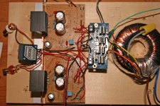
I will be lifting the boards off the aluminum plate. There are 2 pins on the bottom of the heatsinks that I will fit into holes in the plate so as to help keep the 1875 from heating too much. I haven't actually powered up the amp while sitting on the aluminum. I had put it there to see how it would fit and figure out the best layout.
Once everything including the star ground is secured on the aluminum plate it will fit into a wooden box.
I have thermal paste on the pads and a nylon washer holding the 1875 to the heatsink. I could use pads as I have some on hand. Which would work best?
I will be lifting the boards off the aluminum plate. There are 2 pins on the bottom of the heatsinks that I will fit into holes in the plate so as to help keep the 1875 from heating too much. I haven't actually powered up the amp while sitting on the aluminum. I had put it there to see how it would fit and figure out the best layout.
Once everything including the star ground is secured on the aluminum plate it will fit into a wooden box.
Typical, would be to put paste&pad between LM1875 and heatsink and then use a shoulder washer (has ridge to hold screw threads away from metal). If you don't have a shoulder washer, then two layers thermal tube and a nylon washer for the screw. Confirm with ohmmeter lack of conductivity between screw and tab and confirm with ohmmeter lack of conductivity between tab and heatsink.I could use pads as I have some on hand. Which would work best?
P.S.
Don't wait to employ the power star ground. See if the less complicated grounding (removing ground loops) happens to cool off the amplifier.
I propose to run a shortest length cable jumper between the 0v of the right amp to the 0v of the left amp, and then run 1 PG+ and 1 PG- from the rectifier board to the centerpoint of the 0v cable jumper. That's just like the little schematic posted previously. Try to un-complicate--there is 1 planet earth so the correct number of grounds is 1. Having met once they should not again meet--you need one ground, one (1). That will probably cool off your amp.
Kudos. That is an awesome safety enhancement for the U.S. and Canada. Yes, in our area, it is best if there is no touchable metal.Once everything including the star ground is secured on the aluminum plate it will fit into a wooden box.
You need to ground that aluminum sheet directly to earth ground (round/3rd pin of the mains cable). However, you may choose to use a ground loop breaker circuit between aluminum sheet to power star ground in case you want to use a grounded music source, such as a computer. The "ground loop breaker" circuit prevents the super loud hum of duplicate grounding, aka ground loops. The computer, she will earth ground your RCA jacks. The amplifier chassis must be firmly grounded when it has exposed metal. Ut-oh! To resolve this conflict of duplicate grounds, you may need a ground loop breaker circuit. Fortunately, that thing isn't difficult to make.
P.S.
The datasheet for LM1875, from the manufacturers, advises a DC power supply. Have you got plans for that yet? See post#1. In case it were a mystery, Post#1 is advising 4 or 5 of 2200uF 35v caps per each rail, following the bridge rectifier, to stiffen all that loud racket into reasonable quality DC power. You'll probably need some caps (approximate location for cap bank is at power star, closely and equally between the amplifier boards). One easily observable benefit of good DC power is good bass.
Last edited:
Hi Daniel
Well some things are moving ahead and something backwards 🙁
As you can see I have moved everything to a wood board and rewired the rectifier; also added a pot. There are 2 4700uf / 50 caps on the underside of the rectifier board. The ground wires are wired to a single point which will be bolted to the aluminum plate. It's hidden under the rectifier board in the photo.
The AC into the rectifier is 16.85 while the DC out is around 22. which seems about right to me. The only problem now is DC offset on one channel is 21V- 😱. The other channel is almost zero. Somehow I have buggered something up. Where should I start checking?
Thanks again for all your help. This project has been a great learning experience for me.
Attachments
Well - I checked the DC offset at the speakers again last night and now they are both at 21V. I've messed something up but can't figure it out 😱
Any suggestions would be greatly appreciated. 🙂
cheers
Any suggestions would be greatly appreciated. 🙂
cheers
I tried measuring the 4 big caps using the capacitance settingon my multimeter. First a drained the caps with a small resistor then took the measurements but it doesn't make any sense to me. 😕 They measure between 9.28 and 9.32nf. They are 470nf capacitors. What am I missing here.
Well - I checked the DC offset at the speakers again last night and now they are both at 21V. I've messed something up but can't figure it out 😱
Any suggestions would be greatly appreciated. 🙂
cheers
The smaller electrolytic capacitors near the LM1875 seems to be bulged out to me as compared to previous photos, have a closer look & as of now don't connect any spk.
You measured them in the circuit or out of it?
Because in it you can't. All the other components will drain its voltage down rendering the measurement useless.
Because in it you can't. All the other components will drain its voltage down rendering the measurement useless.
I have only one thought on the latest effort. It is probably necessary to clean up the Audiosector Inspired Rats Nest wiring and use a seemly color code for it, such as blue for v-, green for 0v-ground, red for v+, and black for signal+. It also needs a twist and tidy job--see other amplifier build photos for reference (proper build does not look like a cable factory imploded). If you make the cabling much neater then there should be less accidents.
For your safety, please use solder connections instead of mini screw terminals. Having the dodgy things loosen the connection, fry the chip and send offset to fry the speaker, is not a convenience.
For speaker safety, when testing (or anytime), be sure to use a capacitor in series with speaker negative, for blocking DC accidents. Any speaker at your workbench, should have a protection added.
P.S.
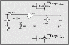
VDM+array power could have given you more dynamic punch (more peak power), deeper 3d imaging, wider right-left imaging, amp board power decoupling more likely to work in more conditions, and is better equipped to ignore/survive cabling layout errors. The price for it is very low. See the schematic and notice the 1N540X diodes are helping provide the VDM power function. Notice that DC power is needed (see post#1 for DC power board examples).
For your safety, please use solder connections instead of mini screw terminals. Having the dodgy things loosen the connection, fry the chip and send offset to fry the speaker, is not a convenience.
For speaker safety, when testing (or anytime), be sure to use a capacitor in series with speaker negative, for blocking DC accidents. Any speaker at your workbench, should have a protection added.
P.S.
VDM+array power could have given you more dynamic punch (more peak power), deeper 3d imaging, wider right-left imaging, amp board power decoupling more likely to work in more conditions, and is better equipped to ignore/survive cabling layout errors. The price for it is very low. See the schematic and notice the 1N540X diodes are helping provide the VDM power function. Notice that DC power is needed (see post#1 for DC power board examples).
Attachments
Thanks for all your suggestions.
Good observation availlyrics- I replaced both those caps. On one amp the DC offset is down to almost zero. The other is still around 21V so something else is still messed up there. Might it be the LM1875 itself?
Daniel- I think I am going to replace the Audiosector board with a different regulator once I have resolved the problem with the DC offset.
Any additional advice would be very much appreciated.
cheers!
The PCB isn't a problem except for lack of a 0v output (for which PG+ and PG- can be wired together to create the 0v), but rather the RF output of the MUR as used on that board can annoy audio amplifiers and radios, causing extra heat and poor functionality. This broadcast is far too high pitched for the PSSR of miller comp type amplifiers and could cause the need of added compensation (or much larger output devices to deal with the rather irresponsible heat consequences).Daniel- I think I am going to replace the Audiosector board with a different regulator once I have resolved the problem with the DC offset.
Possible replacements include:
8 of 1N5403 for dual bridge
8 of 1N5403 for dual bridge
8 of 1N5404 for dual bridge
8 of 1N5405 for dual bridge
8 of 1N5406 for dual bridge
8 of 1N5407 for dual bridge
2 of KBPC1004 for dual bridge (any KBPC100X)
2 of KBPC1604 for dual bridge (any KBPC160x)
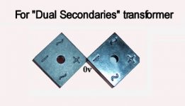
**1 of KBPC2504 is the de-facto industry standard for use with center tap transformers; however a pair of smaller units can be used with dual secondaries transformers.
Here, attached is the dual bridge function of the audiosector board, except with standard diodes that may be tamer and the KBPC100X's shown (or KBPC160X) have a lower pitch (tamer) and can be bolted to an earth grounded metal part to reduce the RF broadcast. The KBPC1004's shown are well marked and easy to use. Bolt them to an earth grounded metal part of the enclosure--this is easily feasible when they are mounted on the bottom side of your power supply board.
Attachments
Last edited:
That's Virtual Dual Mono.What is VDM power?
This happens if a negative regulator and a positive regulator are used per each LM1875 chip, individually so that each channel has somewhat "private" power. In this case, the regulators block crosstalk of the stereo pair so that you get the same wide stereo as monoblocs or dual mono can provide. That's less expensive but not so easy to install.
However, the partial isolation and less voltage drop can be done with diodes instead, very easy to do, as shown in this schematic with the 1n5405's:
See also the forward voltage drop graph of the 1N540X series. I think that might be useful.
Last edited:
Are you sure?..............
**1 of KBPC2504 is the de-facto industry standard for use with center tap transformers; however a pair of smaller units can be used with dual secondaries transformers. .............
The losses (heat) through each bridge rectifier in a dual rectifier dual secondary is equal to the losses through the single bridge rectifier connected to a centre tapped secondary.
Instead of reading and believing build guides, I checked with the sketch pad to "see" the action: The diodes that contact V+ and the diodes that contact V- are doing the same amount of work for both center tap and dual. Yes, you're correct. Thanks!Are you sure? The losses (heat) through each bridge rectifier in a dual rectifier dual secondary is equal to the losses through the single bridge rectifier connected to a centre tapped secondary.
Thanks guys- Could someone explain what components are involved in controlling the DC offset at the speakers. I was thinking of working backwards from the speaker outputs replacing each cap and resistor one at a time until I find the problem. Does this make any sense?
Daniel- Regarding the PS; right now I have the v0 from both amp boards and one of PG+ and one PG- tied together to form a star ground. It's tucked under the rectifier board so you can't see it. Is that how it should be or should I use both PG+ and PG- wires?
PG+ and PG- tied together to form 0v at the rectifier board is really quite normal for dual bridge. This happens to locate power star ground at the edge of the power board.Daniel- Regarding the PS; right now I have the v0 from both amp boards and one of PG+ and one PG- tied together to form a star ground. It's tucked under the rectifier board so you can't see it. Is that how it should be or should I use both PG+ and PG- wires?
OR
At your option, you can extend one PG+ cable and one PG- cable (of identical length and gauge) out to form one 0v at central power star ground, located equally closely to the amplifier boards. That option may have a different tone but doesn't change dc offset. The hookup is not different except for cable length--The PG+ to PG- jumper is merely longer.
The ac coupling, input cap and nfb-shunt cap needs to be in good shape, not shorted not bypassed by accident/miswire.prezden said:Thanks guys- Could someone explain what components are involved in controlling the DC offset at the speakers. I was thinking of working backwards from the speaker outputs replacing each cap and resistor one at a time until I find the problem.
Also you might want to check and see if the DC voltage is reasonably similar on the V+ and V- rails (not severely lopsided).
Also check to be sure the input load is present and installed right.
Notice that if a chip is fake or a previously broken authentic chip producing 1 rail's worth of offset, then if you still want to use it, a capacitor in series to the speaker cable is REQUIRED so that it *might* work but that is not a guarantee. For longer term use, observe the charge of that cap with the voltmeter and make sure that the charge polarity matches up sensibly with the capacitor's markings (not charged backwards).
Last edited:
prezden,
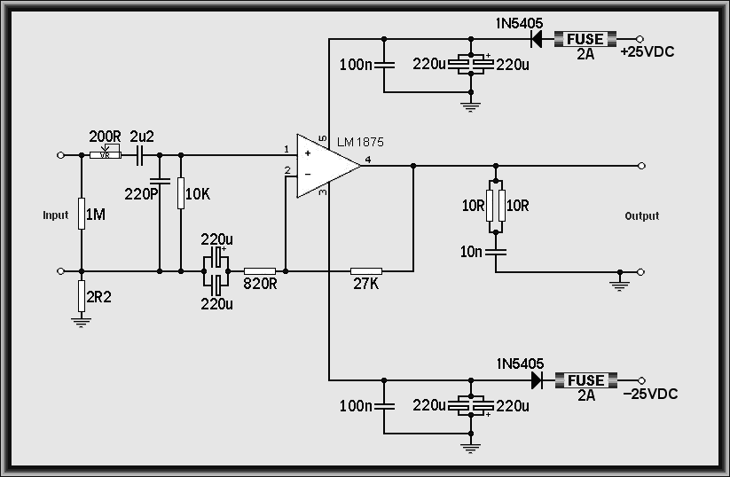
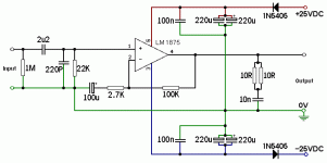
From 2007, the party voiced LM1875 with a better track record, see attached schematics with the 100k feedback resistor and 2.7k feedback shunt resistor.
Do you like the color coded schematic or the normal black and white schematic?
Which schematic is easier to read?
From 2007, the party voiced LM1875 with a better track record, see attached schematics with the 100k feedback resistor and 2.7k feedback shunt resistor.
Do you like the color coded schematic or the normal black and white schematic?
Which schematic is easier to read?
Attachments

- Home
- Amplifiers
- Chip Amps
- Beginner's Gainclone, HiFi LM1875, The Amplifier Board