So i'm confused a little now.
Is this the original preamplifier, are we speaking about the same thing?
Is this the original preamplifier, are we speaking about the same thing?
Attachments
Last edited:
Suppose the correction isn't for this preamplifier,i can't see any R18=68K//C4=47nf ?This is it, yes.
Where i can find this circuit?No, it's quite another circuitry.
Best regards!
Well, it's top secret 😉!
Look back to #77, where I've posted the link. But you have to be an ELEKTOR »member« to download it, or have a subscription to the magazine.
Best regards!
Look back to #77, where I've posted the link. But you have to be an ELEKTOR »member« to download it, or have a subscription to the magazine.
Best regards!
post80 .asc
LTspice can't find bc550c model.
The BC550C model is from Bob Cordell. I've added them to my LTspice library so I don't have to put .include "Cordell-Models.txt" on every new schematic. Get them here: CordellAudio.com - SPICE Models
The schematic that thimios posted is the original supra schematic and basically the one I modelled in LTspice. The upgraded version with multiple LT1028 in parallel is top secret just like Kay said; it hasn't been attached here anywhere and I haven't seen it myself.
Another take at the LT1028
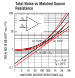
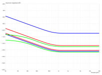
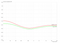
In another thread regarding the use of the LT1028 as a phono preamplifier in a German forum somebody pointed at the total noise diagrams of its datasheet and wrote that the influence of the bias cancellation is only relevant at higher impedances. I've combined those diagrams and tried to derive some useful information from them. This is what I understand: Since the graphs match up pretty good most of the time, the cancellation circuit seems to be effective in that the total noise for an unmatched circuit with RS is about equal to the matched circuit with 2xRS, which should be inherently noisier due to the doubled impedance. Matching the source resistance is only possible with MC systems though, since the impedance of an MM system changes from its DC resistance at the lower end (say 500R) up to around 30k with the usual 47k resistor at the preamp's input, while the RIAA network's impedance stays fairly constant (say around 300R) and rather low for overall low noise. Hence the 'updated' supra 2.0 might be a better (but rather more expensive) choice for MC systems, but certainly not for MM.
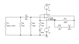
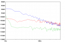
Since I had the stuffed circuit board ready and a spare LT1028 in the parts bin, I did a little comparison between it and the NE5534A. Due to the varying impedance of the MM system and me not having one at home right now, I settled on terminating the preamp's input with a single resistor, but for two different frequencies. What I had at hand were 680R and 470k, which, in parallel with the 6k8 input impedance of the preamp, resemble the cartridge's impedances at around 170Hz and 13.6kHz, respectively. To compare apples to apples I only took the corresponding readings from the spectrum:
You can see the test circuit and the whole graphs attached (measured with ARTA and then re-drawn for better legibility). They clearly show that the LT1028 isn't that much better with moderately low impedances (~614R) and does not perform well with source impedances above 1k (470k in parallel with 6k8 is around 6k3), which is perfectly in line with the datasheet:
The LT1037 looks really interesing and might be a better alternative to the NE5534A at MM-impedances, although it's still pretty pricey in direct comparison. Unfortunately I don't have one in the parts bin, else I would have tested it right away 😉.
In another thread regarding the use of the LT1028 as a phono preamplifier in a German forum somebody pointed at the total noise diagrams of its datasheet and wrote that the influence of the bias cancellation is only relevant at higher impedances. I've combined those diagrams and tried to derive some useful information from them. This is what I understand: Since the graphs match up pretty good most of the time, the cancellation circuit seems to be effective in that the total noise for an unmatched circuit with RS is about equal to the matched circuit with 2xRS, which should be inherently noisier due to the doubled impedance. Matching the source resistance is only possible with MC systems though, since the impedance of an MM system changes from its DC resistance at the lower end (say 500R) up to around 30k with the usual 47k resistor at the preamp's input, while the RIAA network's impedance stays fairly constant (say around 300R) and rather low for overall low noise. Hence the 'updated' supra 2.0 might be a better (but rather more expensive) choice for MC systems, but certainly not for MM.
Since I had the stuffed circuit board ready and a spare LT1028 in the parts bin, I did a little comparison between it and the NE5534A. Due to the varying impedance of the MM system and me not having one at home right now, I settled on terminating the preamp's input with a single resistor, but for two different frequencies. What I had at hand were 680R and 470k, which, in parallel with the 6k8 input impedance of the preamp, resemble the cartridge's impedances at around 170Hz and 13.6kHz, respectively. To compare apples to apples I only took the corresponding readings from the spectrum:
Code:
		170Hz	13.6kHz
--------------------------------
LT1028  @680R	-122dBV
NE5534A @680R	-122dBV
LT1028  @470k		-104dBV
NE5534A @470k		-123dBV
You can see the test circuit and the whole graphs attached (measured with ARTA and then re-drawn for better legibility). They clearly show that the LT1028 isn't that much better with moderately low impedances (~614R) and does not perform well with source impedances above 1k (470k in parallel with 6k8 is around 6k3), which is perfectly in line with the datasheet:
Code:
Best Op Amp for Lowest Total Noise vs Source Resistance
-------------------------------------------------------
Source		Best opamp	Best opamp
resistance *1	@ 10Hz		@ 1kHz
-------------------------------------------------------
0 to 400 	LT1028/LT1128 	LT1028/LT1128
400 to 4k 	LT1007/1037 	LT1028/LT1128
4k to 40k 	LT1001 		LT1007/1037
40k to 500k 	LT1012 		LT1001
500k to 5M 	LT1012/LT1055 	LT1012
>5M 		LT1055 		LT1055

*1: Source resistance is defined as matched or unmatched, e.g.,
RS=1k means: 1k at each input, or 1k at one input and zero at the other.
The LT1037 looks really interesing and might be a better alternative to the NE5534A at MM-impedances, although it's still pretty pricey in direct comparison. Unfortunately I don't have one in the parts bin, else I would have tested it right away 😉.
Attachments


How did you include them in the LTspice library?The BC550C model is from Bob Cordell. I've added them to my LTspice library so I don't have to put .include "Cordell-Models.txt" on every new schematic. Get them here: CordellAudio.com - SPICE Models............
How does LTspice not overwrite anything you change in the library?
I have available the new SUPRA 2 article with four LT1028 in parallel as a PDF document, because I'm a so called ELEKTOR gold member. But I'm afraid that I can't offer it here without copyright infringement. Sorry!
But, as Preamp said, it might not even be worth to be considered as a real progress as far as you use a MM cartridge.
Best regards!
But, as Preamp said, it might not even be worth to be considered as a real progress as far as you use a MM cartridge.
Best regards!
How did you include them in the LTspice library?
Add the models to \LTC\lib\cmp\standard.bjt
How does LTspice not overwrite anything you change in the library?
Dunno. I'm old school in terms of updates, so I only do it once a year - never change a running system, you know 🙂 - and then make a backup beforehand. IIRC the last update did not screw my modified libraries, and if it did, I'd simply add the models again. Much less of a hassle than adding an .inc to every new draft or use a template each time...
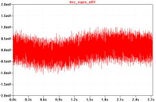
Brought my vintage turntable home today and hooked up the cheap Audio Technica AT91 to my testbed-preamps with some cat.7+ cable. Shielding was basically non-existent though, since the preamp is not encased in any way, which resulted in most of the noise being 50Hz mains and something around 16kHz and 18kHz coming from the computer itself.
The LTspice-integrated RMS noise figures for the below waveform plots are ~250uVRMS for the supra and ~300uVRMS for the NE5534A, most of that being 50Hz mains hum.
I recorded a track with audacity, normalized it by a couple of dB, and played it back. The noise (even that mains hum) is already low enough that it is not bothersome for normal listening. In the silent passages between two tracks for example I can hear it, but certainly not at normal listening levels. Via headphones it might be a little annoying (didn't test it), but I'm not planning to listen to any record via headphones anytime soon...
Attachments

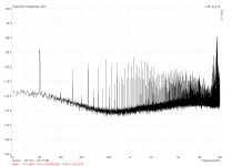
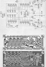
I've had a look at the schematic for the supra 2.0 now. Since the input is terminated with 100pF and 47k, it's probably meant to be used with MM systems. The design comprises of four non-inverting LT1028 working into an inverting buffer with a total gain of 45dB at 1kHz, followed by a three-stage active RIAA network including a 10Hz and a 50kHz pole. The pcb is solely surface mount and the four other opamps are LM837 in a single package. Not much to complain so far, since all parts are standard E48 values and thus easily available. Overload performance should be as good as it gets, since all the gain is in the first stage with the others basically being buffers only. Reducing the overall gain would yield some more headroom (I've opted for 35dB instead of 45dB), but that's another story.
Of course I had to simulate the circuit with a noiseless inverse RIAA network and the cartridge values of 410R and 480mH, and here the simulator seems to confirm my concerns. See the results attached. With the LT1028 model for the parallel input quad and my NE5534A model for the other opamps, the output noise in the range of 20Hz to 20kHz integrates to almost 830uV. Using my NE5534A model for all eight opamps, the result is certainly a lot better with an RMS value of only 115uV! Using the NE5534A model from TI's website the result is even better still.
The sim might not hold true in the real world (the absolute values certainly won't), but if I were the inventor of the supra 2.0, I'd certainly get myself some NE5534A and pop them in there to be sure - they're not that expensive after all 🙄.
"my NE5534A model" is simply the UniversalOpamp2 of LTspice with the following model parameters:
Avol=1Meg GBW=10Meg Slew=9Meg
ilimit=35m rail=2 Vos=0.5m phimargin=45
en=3n5 enk=30 in=400f ink=1k Rin=100k
The last line is most relevant for noise simulations, with en and in resembling the datasheet values for voltage and current noise, respectively. enk and ink resemble the frequency knee where the shot noise takes over; I've chosen them empirically to match the graphs from the datasheet.
Attachments

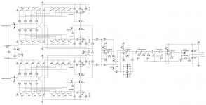
Here's another idea, the Supra^2 (supra squared) with a balanced input stage. Noise will be 3dB worse wrt the single-ended version, but the picked up noise (especially mains hum) should be much lower due to the inherently better common mode rejection of the instrumentation amp. So if you've got some BC's left from a batch, grab the chance and sink them here 😎.
Attachments
Quite nice 😉!
Though, I don't see no benefits from using WIMA MKP10's for C1, C2, C9, C10, C11, C21 and C22, respectively. MKP4's for 100 volts will do. The difference is the capability of pulse currents, which we don't really need within a RIAA equalization network.
Best regards!
Though, I don't see no benefits from using WIMA MKP10's for C1, C2, C9, C10, C11, C21 and C22, respectively. MKP4's for 100 volts will do. The difference is the capability of pulse currents, which we don't really need within a RIAA equalization network.
Best regards!
I don't get it why you parallize BC857? What for? If you are really after low noise, the BC857 is the wrong transistor from the start.
The only thing you get is a lot of nonlinear capacitance and HF problems.
By the way a MM input stage has the lowest noise with ONE transistor running at about 50 uA collector current.
Also i don't understand what a balanced configuration for a MM/MC preamp is good for?
It does not matter if one end of a floating MC coil is connected to GND or not.
If the coil is floating CMRR is not affected. Think of it...
The biggest problem of your circuit might well be PSRR and a good regulated power supply brings you the most for your money.
Best,
Udo
Though, I don't see no benefits from using WIMA MKP10's (...). MKP4's for 100 volts will do.
They will, but MKP4's are not available from Reichelt! MKS are a lot smaller, but after having read this I'll never use polyethylene caps again when an equivalent polypropylene is available from Reichelt 😛
Yes, tan delta, i.e. dielectric losses, by far is lower in polypropylene foil capacitors.
Best regards!
Best regards!
- Home
- Source & Line
- Analogue Source
- BC550 BC560 Very low noise RIAA