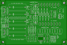
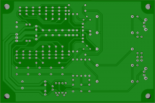
I have bought a PCB for this phono stage from ebay, link here:
pcb preamplificatore phono SLN ELEKTOR preamplifier super low noise | eBay
My question is can I use the KSC1845/A992, allowing for pinout differences? I ask as it is mentioned the input capacitance of this stage is higher than the usual MM loading levels (allowing say 100pF for tonearm cable) and these transistors have a lower cob than the BC550/560 in the schematic... is this a good idea or bad? The 1845/992 are slower than the 550/560 and also low noise
the pcb is now on baya for sale , 5pz.I have bought a PCB for this phono stage from ebay, link here:
pcb preamplificatore phono SLN ELEKTOR preamplifier super low noise | eBay
My question is can I use the KSC1845/A992, allowing for pinout differences? I ask as it is mentioned the input capacitance of this stage is higher than the usual MM loading levels (allowing say 100pF for tonearm cable) and these transistors have a lower cob than the BC550/560 in the schematic... is this a good idea or bad? The 1845/992 are slower than the 550/560 and also low noise
tks
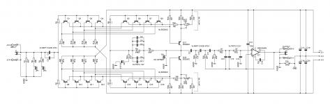
Here's my take on this design. Added some useful things on the board, like a subsonic filter used by Douglas Self and the damped cartridge loading scheme of Bob Cordell's VinylTrak. Simulates pretty good, I'll have to see how the reality stacks up. I had already built a prototype of the supra itself on a small pcb, but it showed some traces of oscillation. That's why I added in some base stopping resistors, hoping that they're sufficient in case they're needed (don't hope so; they add some noise after all). Won't have the boards made this year, though.
Attachments
Hi
If you use cartridge damping a la Bob you have to lessen the impact of time constant 75us over 8kHz. How did you realise this?
If you use cartridge damping a la Bob you have to lessen the impact of time constant 75us over 8kHz. How did you realise this?
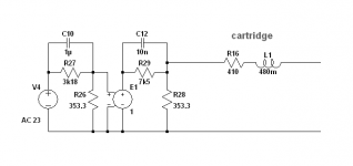
In this case I damped the cartridge completely, so that the response has a -3dB point at 2122Hz already. This way I can leave out the cap for 75us altogether. Noise will be a bit higher, but the input is almost insensitive to input capacitance! If you go the way Bob went and find a compromise in between, you can put a resistor in series with the 75us-cap and adjust it accordingly.
I thouth that the noise will be lower when load resistance is lower... Is it in the case of this pre that the noise come mail fro 47k cartridge load?
BTW wich cap from yor pre version makes 75us?
BTW wich cap from yor pre version makes 75us?
I used to think that also, but apparently current noise is the culprit here. To quote Douglas Self: "Johnson current noise is just the usual Johnson voltage noise applied through the resistance in question".
Another thing is that the input signal above 2kHz (and thus the corresponding input noise, too) is no longer attenuated by the RIAA network's 75us pole, since there is none.
Like I said, there is no 75us cap here. It would go in parallel with R8, but then the whole feedback network would have to be recalculated to keep RIAA response accurate. You could put a simple RC network at the output as an alternative (R in series, C to ground).
The noise comes from the total resistance of at the input => mainly the cartridge.I thouth that the noise will be lower when load resistance is lower... Is it in the case of this pre that the noise come mail fro 47k cartridge load?
BTW wich cap from yor pre version makes 75us?
I used to think that also, but apparently current noise is the culprit here. To quote Douglas Self: "Johnson current noise is just the usual Johnson voltage noise applied through the resistance in question".
Another thing is that the input signal above 2kHz (and thus the corresponding input noise, too) is no longer attenuated by the RIAA network's 75us pole, since there is none.
Like I said, there is no 75us cap here. It would go in parallel with R8, but then the whole feedback network would have to be recalculated to keep RIAA response accurate. You could put a simple RC network at the output as an alternative (R in series, C to ground).
OK,
but how do you measure riaa accuracy then, white noise on the record and scope?
I for one use LTspice and rely on the sim being reasonably accurate in the real world, too 8). The values shown (with the cartridge shown, a cheap AT91) are accurate to within 0.7dB, even with real-world tolerances for the feedback components. Doesn't look like much, but using 47k and some picofarads for a MM cartridge you're off by at least 2-3dB at the high end, which, in addition, is heavily influenced by cable- and preamp-input-capacitance.
Hi
If I uderstood right you are setting in ltspice to the voltage source the inductance, capacitance and resistance identical like for at 91 and run ac small signal?
If I uderstood right you are setting in ltspice to the voltage source the inductance, capacitance and resistance identical like for at 91 and run ac small signal?
Elektor India wayback in 1982 July/August edition published "Super low noise Preamp for MM Cartridge". As per my memory the circuit used BC550/560C devices in parallel. Some of our Indian DIYAudio member may have copy of this edition.
That's right. Add an ideal RIAA curve to the source (there're many ways to do that) and the preamp's output should be a flat curve.
The simulated noise performance of this circuit is a little bit worse than with a 'datasheet ideal' NE5534A instead. Reducing the input transistors from 4 sets to just 1 even shows a little less noise, which would defeat the whole practice of paralleling multiple input devices, so I think the sim is a little off here. I will build the supra and an opamp version with identical gain and make a real-life comparison.
The simulated noise performance of this circuit is a little bit worse than with a 'datasheet ideal' NE5534A instead. Reducing the input transistors from 4 sets to just 1 even shows a little less noise, which would defeat the whole practice of paralleling multiple input devices, so I think the sim is a little off here. I will build the supra and an opamp version with identical gain and make a real-life comparison.
Attachments
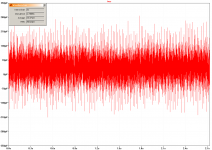
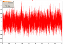
Built two prototypes - one of the supra and one of a simple non-inverting opamp circuit using the same RIAA network scheme and a socketed NE5534A. I powered them with a +-15V lab supply, shorted the inputs and recorded samples of almost 3 seconds each, using ARTA. The recorded data was then saved to a text file, imported into LTspice, and let the waveform viewer do the dirty work of integrating the voltage. Note that the waveforms show some periodically repeating spikes, which is simply noise picked up from the environment or the computer itself.
The NE5534A has a noise voltage of 65uV, while the supra is considerably lower with 50uV. Looks good so far 😎
In actual use the noise will be somewhat higher due to the cartridge impedance.
The NE5534A has a noise voltage of 65uV, while the supra is considerably lower with 50uV. Looks good so far 😎
In actual use the noise will be somewhat higher due to the cartridge impedance.
Attachments
That's right. Add an ideal RIAA curve to the source (there're many ways to do that) and the preamp's output should be a flat curve.
The simulated noise performance of this circuit is a little bit worse than with a 'datasheet ideal' NE5534A instead. Reducing the input transistors from 4 sets to just 1 even shows a little less noise, which would defeat the whole practice of paralleling multiple input devices, so I think the sim is a little off here. I will build the supra and an opamp version with identical gain and make a real-life comparison.
great!
please send asc file without 75us cap
thank you in advance!
ELEKTOR themselves have an upgraded version of the SUPRA RIAA preamp!
Which is not thought through thoroughly, though. (What a sentence 😀)
First point is that the current noise of the LT1028 is rather high, which is detrimental at least for the MM version and totally swamps the better voltage noise specs. Second point is that the LT1028 has a built-in bias current cancellation circuit which makes the noise behaviour even worse in this case, as pointed out by Self in Small Signal Audio Design. Third point is that using several expensive (!) opamps in parallel totally defeats the purpose of this design. All that said, one would probably be better off using multiple NE5534A (not NE5532A, as they're a little bit worse) in parallel! That would be cheaper for sure and probably even better than with LT1028's - but not cheaper than the original supra.
please send asc file without 75us cap
Sorry, missed that.
Attachments
- Home
- Source & Line
- Analogue Source
- BC550 BC560 Very low noise RIAA