I only mentioned overdrive as (some) users will abuse their
amps ,

 New Year is coming
and my clamped VAS is ready.
[see schema below...]
realize . So why not limit clipping to mostly H2 and clamp
accordingly to be on the safe side...
In many commercial amps (Hi-Fi and instrument) clamping
is employed as a rule..I personally never run my projects
overdriven as that defeats the purpose😀 but who knows??
,the wife or kids could screw up.
Anyways, happy holidays and a better New year.
OS
amps ,
New Year is comingand my clamped VAS is ready.
[see schema below...]
exactly, and some are either too inebriated or oblivious toBy Nico - HF clipping destroys tweeters
realize . So why not limit clipping to mostly H2 and clamp
accordingly to be on the safe side...
In many commercial amps (Hi-Fi and instrument) clamping
is employed as a rule..I personally never run my projects
overdriven as that defeats the purpose😀 but who knows??
,the wife or kids could screw up.
Anyways, happy holidays
and a better New year.OS
An externally hosted image should be here but it was not working when we last tested it.
Nico Ras said:HF clipping destroys tweeters,
ostripper said:I only mentioned overdrive as (some) users will abuse their
amps ,
Nico, OS,
Happy holidays (whatever)!
The amp needs to be examined in simulation during clipping. Some components, VAS maybe, can be subject to over current, so depending on the design, the tweeters are not the only thing at risk.
Low frequency clipping will blow tweeters too - harmonics.
Don't drink too little !!

This amp is actualy easy to assemble… Piece of Cake… see!
😀 😎 🙂 🙂 VERY unique... Amp cake... thought I seen
everything...
Happy holiday.. Baromega!!
OS
boraomega said:I was "naughty" again... some more ideas...
Hi Bora,
a very elegant design. I support full complementary symmetry and modified Le Gecko yesterday afternoon with the described output stage. Ii is fitted with 2SK1058/2SJ162 and I added MJ15003/4 to each side.
The link shows the original Le Gecko for those interested. There are a few similarities but I would like to study your design a little.
Anyway guys for those who celebrate Xmas - have a very Merry Christmas and prosperous New Year!

http://www.digisec.co.za/ras/music/Geck MkIV.pdf
Looks promising Nico, but as I said previously, simulation is just a poor-man-delight to give you impression that you’ve done something that cost you nothing. Once you build it you will face the truth. Maybe one day, simulation will be precise and powerful enough to mimic real world successfully, but till then… I’ll be prone to categorize it as “petting” at best… 😀
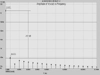
😀When compared to the original design without IGBT (mosfet only) the H2 is 4 dB worse at -105 dB but slew is the same.
However the design without using IGBT although revealing an overall higher THD, H5, H7 and H9 is an order of magnitude lower than with the IGBT. (according to sims anyway). I cannot make any real measurements because I will only go back to work on the 12th January.
Sound wise there is no audible difference between the two amplifiers.
I cannot see any advance adding four transistors to achieve an IGBT output stage and a lateral MOSFET output stage.
Okay guys I am at an age where a Christmas afternoon snooze after a big dinner is mandatory. Enjoy the rest of the day.
Hi Borivoje,
I think I spelled that right right.
I still like your design and will definitely make a practical amplifier as soon after I am back at work.
I will make both versions with IGBT and MOSFET only and will report back when done. Thanks for your valued contribution.
Kindest regards
Nico
I think I spelled that right right.
I still like your design and will definitely make a practical amplifier as soon after I am back at work.
I will make both versions with IGBT and MOSFET only and will report back when done. Thanks for your valued contribution.
Kindest regards
Nico
Dr.Bora;
I really like this design - I will probably try to use more common JFET like 2n4416 and 2n5285, since I cannot get the Japanese FETs.
ostripper;
You really have made amazing progress ! - we think the same when it comes to clipping behaviour.
Please, does anybody have a good design philosophy for minimizing IMD at the expense of THD ???
balaboo: "I will probably try to use more common JFET like 2n4416 and 2n5285, since I cannot get the Japanese FETs"
That is OK as long as you try to provide P and N channel FET-s with matched Idss. Those Jap FET-s are available from "BDent".
That is OK as long as you try to provide P and N channel FET-s with matched Idss. Those Jap FET-s are available from "BDent".
I’ll be really delighted to see someone is building any of those ideas, because I certainly won’t be able to give it a try in a foreseeable future (few months… maybe even half a year). Just it shouldn’t be forgotten that some components should be added in a real circuit like supply rails decoupling, shunted output coil if it is suppose to work with speakers with significant reactive character and Boucherot (Zobel) cell on output.
by balaboo -You really have made amazing progress ! - we think the same when it comes to clipping behaviour.
Thank you for comment but with knowledge comes headaches🙁
As far as this topology, Dr. bora is right about simulators,
they are only an "approximator". Lucky for me , I have
2 "real' working amps with this topology and can
see behaviors of different device choices. Some devices,
such as the new fairchild ksa1381, saturate very easily at
clipping giving a very harsh result (but no
 )with
)with plenty of H5/7/9+etc.
I've tried the new ksa350/40's both in virtual and real world.
they saturate much less but you end up with a"slower" amp.
I'd like to try dr. bora's 2sc2240 but they are hard to find.
(except SMD , which I might go to next..more choices 🙂)
The models are getting better, I can see a notable difference
between the "old" 340/350 model and the KSA clones as
the new model has saturation characteristics included.
BTW - I'm "stealing" bits and pieces of the design and the
improvements are impressive.
OS
ostripper said:
Some devices,
such as the new fairchild ksa1381, saturate very easily at
clipping giving a very harsh result (but no
plenty of H5/7/9+etc.
I've tried the new ksa350/40's both in virtual and real world.
they saturate much less but you end up with a"slower" amp.
Hi OS,
This is simply not the case. I already pointed out that I tried the MJE340/350 in place of the 2SA1381/3503 in your amp and experienced worse clipping behaviour.
There are other factors at play here and blaming the device is not the fix.
Ostripper, 2SC2240/2SA970 are available from "B&D Enterprises" at $0,30 each. It is big problem for me to obtain them but you are there... you shouldn't have any problem. I like them very much and most of my designs in recent years are based on them in pre-stages and for position with up to a 50-70mW dissipation.
- Status
- Not open for further replies.
- Home
- Amplifiers
- Solid State
- Balanced IGBT for amplifier output