You can certainly easily measure and hear edge diffraction. It's one of the many reasons I don't like full-range speakers that don't have any EQ/filtering. You inevitably get a peak-dip in the frequency response of about +2/-2dB just above the baffle step frequency spanning about an octave. At least with multi-way speakers you can stomp it out with the crossover design.So you might be able to measure baffle edge diffraction and deal with it, but can you hear it well enough to want to turn your speakers into woolen creatures?
Solving it by experimentally modifying the baffle could be tedious. I prefer to just sim (with the edge) to find driver locations that seem to work, add large roundovers to the long sides of the baffle and call it a day. Whatever remains after the baffle is constructed just has to be dealt with in the crossover.
Last edited:
I believe in purpose building a baffle and typically work from the driver, where the conditions are set, and move outward. As a DIYer who prototypes this means I'm less likely to be changing the early portions as long as I'm careful to design for function and fit, which is good because I like my throats and rear enclosures to be very solid.one being a limitation in the materials use.
After this it is different. I might extend or change a baffle profile/roundover, or adjoin baffles. There are a number of reasons I might use lighter materials, such as.. they need to be curved, there is much more area to cover, and I might be changing them later. Also there is less pressure here and some of the spectrum has largely become independent by this point. In some respects, once critical frequencies have turned the first corner you might get away with more.
What have we learnt from all the squabbles?
1. wide baffle is not an optimal solution since the low frequency image will suffer.
2. narrow baffle probably not ideal either since common baffle geometry will introduce
diffraction at around 2.5kHz - 4kHz and that is where most xover frequencies between
the mid woofer and tweeter.
Solution:
1. a spherical shape cabinet like B&W if you got the equipment or the skills or the money or slavery.
2. so what we are left at? old squabbling?
I can't tell people what to do but it seems to me personally the best way is to have as narrow baffle as possible BUT have drivers offset AND have some type of offset chamfering (that is non-symmetric chamfering).
Of course if you have all the money in the world then the world is your hubris.
And if you are not going to take care of the diffraction objects near the speakers then the baffle issues won't matter at all.
The evolution in the audio industry is a slow one and one of a handful companies that is leading this is B&W.What have we learnt from all the squabbles?
1. wide baffle is not an optimal solution since the low frequency image will suffer.
Solution:
1. a spherical shape cabinet like B&W if you got the equipment or the skills or the money or slavery.
But such a statement will irritate does who swear by papercones and sildome. Odd isn't it, changes that improve the driver or cabinet performance are reject by so many.
Somehow the F117 Stealth Fighter makes me thing it's something that can be used to minimize diffraction.

Nono, F117 or modern battleships avoid rounded surfaces to prevent radar signals being reflected back to radar receiver. The airplane does not transmit (radar) signals like a speaker. Other method to fool radars is to spray aluminium strips (chaff) as they fly!
Stealth technology - Wikipedia
Stealth technology - Wikipedia
Last edited:
...full-range speakers… add large roundovers to the long sides of the baffle and call it a day.
That works. These have a polygonal approximation of a teardrop in the plan view and at higher frequencies there is enuff beaming that the wavefront does not travel along the baffle.
dave
That works. These have a polygonal approximation of a teardrop in the plan view and at higher frequencies there is enuff beaming that the wavefront does not travel along the baffle.
dave
well if you have wide a$$ cabinets ...
Diffraction falls into the category of Level Dependent Perception of linear phenomena. That means that it becomes more audible as the level increases, much like nonlinear distortion. Many people, I believe, mistake diffraction for nonlinear distortion because of this. But it also means that diffraction will always be audible at some level. The lower the diffraction the louder you can play the system without audible problems.
I go to extremes with diffraction including carefully removing any diffracting object near the speakers even if they are not part of the speakers. I often see peoples setups with equipment cabinets, TV's all kinds of diffracting object placed very near the speakers. (shown above) Bad idea!! I have found that the more I reduced all forms of diffraction the better the sound.
That is the ideal. Unfortunately my current listening room has a lot of opportunity for diffraction to occur, and it is noisy from external sources.
An externally hosted image should be here but it was not working when we last tested it.
The beautiful thing about Diy is that you make it your own. I like working with Schedule 80 PVC pipe for enclosures. It's strong, has a nice curve for the baffle, and can be made to look pretty good.
You can certainly easily measure and hear edge diffraction. It's one of the many reasons I don't like full-range speakers that don't have any EQ/filtering. You inevitably get a peak-dip in the frequency response of about +2/-2dB just above the baffle step frequency spanning about an octave. At least with multi-way speakers you can stomp it out with the crossover design.
Solving it by experimentally modifying the baffle could be tedious. I prefer to just sim (with the edge) to find driver locations that seem to work, add large roundovers to the long sides of the baffle and call it a day. Whatever remains after the baffle is constructed just has to be dealt with in the crossover.
Wouldn't a BSC circuit solve the baffle step problem even for a full range driver?
The compensation just adjusts levels so no, it's not essentially a solution but yes, full range or multi-way have these same concerns.Wouldn't a BSC circuit solve the baffle step problem even for a full range driver?
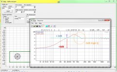
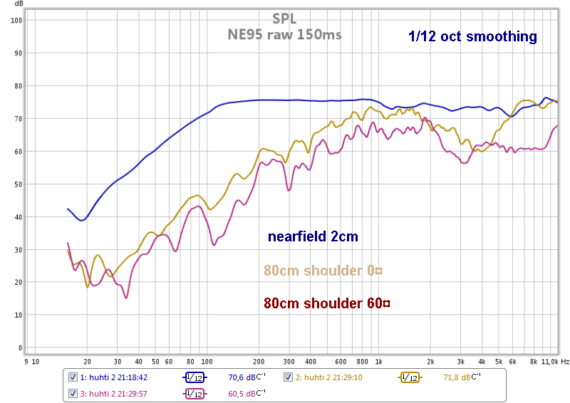
Baffle diffraction is not just that -6dB, there is also some boosting with high Q notch and ripples above it (orange circle). The height and width of the bump depends on baffle/driver relations. A rectangular box shape distributes well, a round or square is more difficult! That's why B&W Nautilus etc. balloon cabinets are not a real solution to the whole phenomenom, it helps only in the highest octave!
Attachments
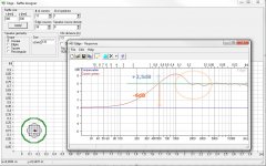
It is also the wider distribution of sound with higher power used for the same response. The extra power has the potential to reflect and interfere.
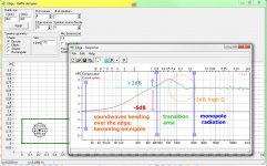
I added some text to show how radition pattern is changing in relation to frequency.
The transition area is the most challenging to eq and very often we must set xo there too. Sometimes it helps, sometimes not!
These don't contain polars, but with these dimensions driver diameter start making beaming above 2kHz.
An externally hosted image should be here but it was not working when we last tested it.
The transition area is the most challenging to eq and very often we must set xo there too. Sometimes it helps, sometimes not!
These don't contain polars, but with these dimensions driver diameter start making beaming above 2kHz.
Attachments
The fact is that our ears are placed laterally at the head
We don't hear what comes directly in front of us because the sound ( wave) has already spreaded and bounced ( the walls...) so we hear an integration of direct and reflected sound.
We don't hear what comes directly in front of us because the sound ( wave) has already spreaded and bounced ( the walls...) so we hear an integration of direct and reflected sound.
Baffle diffraction is not just that -6dB, there is also some boosting with high Q notch and ripples above it (orange circle).
Humps and dips are "local" directivity effects which cannot be fully compensated in axial response without corrupting power response. Please use better diffraction simulator than Edge to study that 😉
^Yes you are right,they can't be eq'd, (I knew that) and Edge tells that too by the way.
My recommended practise is to lowpass well below the ripples! Only the tweeter remains problematic then! The baffle must get narrower as frequency goes up. This is almost impossible to make working throuh all octaves. My AINOgradients follow this principle, dipole bass and midrange operate in linear directivity range below baffle step peak, at the expense of sensitivity.
This is a 4" nude dipole cone
Last edited:
- Home
- Loudspeakers
- Multi-Way
- Baffle Diffraction