Cones and domes have very different off-axis radiation pattern from planars! And soft vs rigid cones have different patterns. In real world, it is very hard to find a driver that behaves like a simulation model or has flat response.
Klippel Online Training

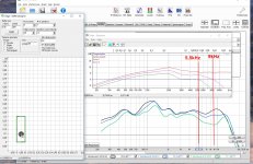
I made a quick and dirty test with a cone in open baffle off-axis vs. The Edge. Besides the ripples in unequalized response, directivity change off-axis looks pretty much the same!
Klippel Online Training
I made a quick and dirty test with a cone in open baffle off-axis vs. The Edge. Besides the ripples in unequalized response, directivity change off-axis looks pretty much the same!
Attachments
Care to go under the surface just a bit on that ?Not really, special delayed crossfeeds can fix that.
I made a quick and dirty test with a cone in open baffle off-axis vs. The Edge. Besides the ripples in unequalized response, directivity change off-axis looks pretty much the same!
What is the point of this? Some kind of response to my message?
By rounding the baffle you give the waves something to (partially) follow so the diffraction happens gradually.. but by using absorbing material on the baffle you are doing almost the same thing through different means.
You should keep in mind that absorption material is almost ineffective for sound traversing at a grazing incidence. Hence, for all practical purposes the felt, or whatever, doesn't do a heck of a lot. Corner radii are much more effective.
Something to chew on Head-related transfer function - WikipediaCare to go under the surface just a bit on that ?
That one is simple - I think 😉. I want the baffle to be acoustically transparent, no interference or conflicting waves of cancellation.You keep mentioning what you want the baffle not to do, but what do you want it to do for you? Are you going to let it make a mess and fix it with absorption? Do you want imaging or spaciousness or both?
Imaging is solved by:
1. Driver placement or distance to one another, for the tweeter and midrange, the closer they are the better but since each tweeter model behaves differently, the optimum distance must be experimented with. The larger the woofer is the less imaging you can control, so woofer size dictates if the position is important or not.
2. The other part is the height of the tweeter and midrange. Traditionally the tweeter height is placed with a person sitting down as the frame of reference, so and average position of 980-1100 mm is often used, but this also depend on if its just MT or MTM configuration.
3. Baffle size and shape as we've talked about.
4. Crossover: Time alignment & Baffle Step Compensation (BSC).
5. Distance between the loudspeakers, toe in/out and tilt is often neglected as a very important part of imaging or spaciousness - Room related.
6. Room Acoustics.
7. Last but not least, a DSP can address some of the issues a loudspeaker has.
Did that answer your questions ?
The reason it has been suggested that headphones can image is the relative lack of non-direct energy. You speak of the size of the sources, or the collective of sources. As diffraction also becomes a source, and one that has uniquely identifiable properties such as time delay and angle to the listener it can be an issue that affects imaging. I don't necessarily agree about the driver size. Some of your other points refer to room reflections which should similarly be taken into account.
Why will you choose to begin with a flat baffle?
Why will you choose to begin with a flat baffle?
I have enough engineering skills to work with other geometrical shapes, but they dictate a completely different construction method and hence will cost more and require other tools, jigs etc. A straight answer to how can't be given since that totally depend on shape(s) and choice of materials which there are plenty to choose from, aka casting, milling, lamination or a combination of them all.Why will you choose to begin with a flat baffle?
One might say that me exploring the ideas of damping and diffusion of an apparent flat surface is an effort to bypass more complex shapes.
PS: Time consumed during development should not be correlated to fixed production methods as they are very different in all cases.
WE have at least two published diy-copies of it
Not a copy, but inspired by, and borrowing the name “ellipsa” from the smaller one.
dave

The tempting thing to do with a wide shallow speaker cabinet is to place it right against the front wall
I read this article recently about using wool on the baffle to tame edge diffraction. He includes measurements:
Diffraction Doesn't Have to be a Problem
Then today I read this, also with measurements included:
Diffraction from baffle edges
So you might be able to measure baffle edge diffraction and deal with it, but can you hear it well enough to want to turn your speakers into woolen creatures?
Diffraction Doesn't Have to be a Problem
Then today I read this, also with measurements included:
Diffraction from baffle edges
So you might be able to measure baffle edge diffraction and deal with it, but can you hear it well enough to want to turn your speakers into woolen creatures?
I know its difficult, but can you describe the imaging, perhaps use a commercial loudspeaker as comparison.Not a copy, but inspired by, and borrowing the name “ellipsa” from the smaller one.
dave
So you might be able to measure baffle edge diffraction and deal with it, but can you hear it well enough to want to turn your speakers into woolen creatures?
Diffraction falls into the category of Level Dependent Perception of linear phenomena. That means that it becomes more audible as the level increases, much like nonlinear distortion. Many people, I believe, mistake diffraction for nonlinear distortion because of this. But it also means that diffraction will always be audible at some level. The lower the diffraction the louder you can play the system without audible problems.
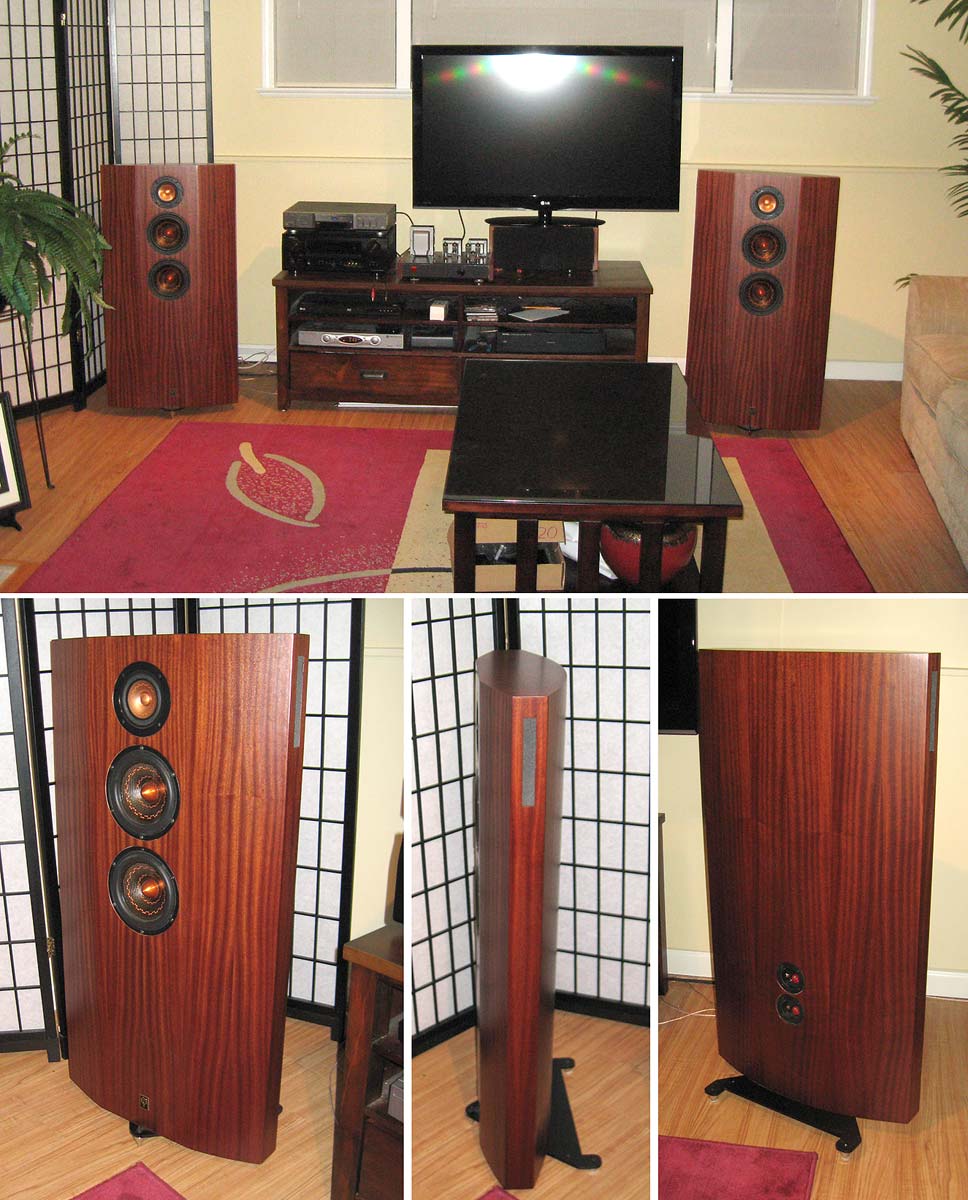
I go to extremes with diffraction including carefully removing any diffracting object near the speakers even if they are not part of the speakers. I often see peoples setups with equipment cabinets, TV's all kinds of diffracting object placed very near the speakers. (shown above) Bad idea!! I have found that the more I reduced all forms of diffraction the better the sound.
You are obviously referring to the visual appeal of the loudspeaker and lets just say that some are appreciated designers while some are not 😉 What I am saying is that to limit the solution to simply using felt on the front is a half hearted attempt at doing the technical aspects full justice.I read this article recently about using wool on the baffle to tame edge diffraction. He includes measurements:
Diffraction Doesn't Have to be a Problem
Then today I read this, also with measurements included:
Diffraction from baffle edges
So you might be able to measure baffle edge diffraction and deal with it, but can you hear it well enough to want to turn your speakers into woolen creatures?
When a car company is working on aerodynamic property's of a car or parts of a car, it usually is not the most appealing thing to look at, rarely is that exactly how it is sold to the customer.
I have noticed two things - and I am not saying this to you exclusively.
1. It looks ugly and I cannot make it beautiful, therefor it is crap.
2. I can't simulate it and therefore its not worth perusing.
Both are equally bad for the maximum effort in exploring the solutions and benefits.
Ask any engineer with enough experience and he or she will tell you: Our best software could not take into account real life issues and unknowns which dictate that we either need to start over or do things in a very unconventional way.
Originality is not achieved by walking in someone ell's footsteps.
An externally hosted image should be here but it was not working when we last tested it.
... can you describe the imaging, perhaps use a commercial loudspeaker as comparison.
That last commercial loudspeaker i spent anytime listening to was the Sonus Faber Ellipsa, and that was when they were 1st introduced.
If our builds do not image well we consider them a failure, these do a particularly good job (and yes Scott, they typically get placed close enuff to the wall to make baffle stepo a non-issue).
Besides being wide and curved backwards, the XO is at 160 Hz, so the driver centre-to-centre is less than a quarter wavelength at the XO avoiding huge swaths of issues that a “normal” cone/dome build have. The midTweeter is well capable of reaching high enuff to not need a tweeter.
dave
This
The lower the diffraction the louder you can play the system without audible problems.
I think you may have misunderstood me. I meant to ask why you want to have half-space (180 degree dispersion) baffling around your drivers. If it is for practical reasons then the answer needn't be difficult, you simply need to choose a size and mitigate the edges or you could blend the two.I have enough engineering skills to work with other geometrical shapes, but they dictate a completely different construction method and hence will cost more and require other tools, jigs etc. A straight answer to how can't be given since that totally depend on shape(s) and choice of materials which there are plenty to choose from, aka casting, milling, lamination or a combination of them all.
One might say that me exploring the ideas of damping and diffusion of an apparent flat surface is an effort to bypass more complex shapes.
PS: Time consumed during development should not be correlated to fixed production methods as they are very different in all cases.
If you have sufficient rounding then the question of placement loses some of its significance and centring the driver is an effective use. It could be as simple as applying a halved heavy cardboard tubing frame around a normal box.
Last edited:
There are ways to make a no compromise design look good dahlquist dq-10 - Google SearchIt looks ugly and I cannot make it beautiful, therefor it is crap.
I understood you 🙂I think you may have misunderstood me. I meant to ask why you want to have half-space (180 degree dispersion) baffling around your drivers. If it is for practical reasons then the answer needn't be difficult, you simply need to choose a size and mitigate the edges or you could blend the two.
If you have sufficient rounding then the question of placement loses some of its significance and centring the driver is an effective use. It could be as simple as applying a halved heavy cardboard tubing frame around a normal box.
What I am saying is that exploring other geometrical shapes such as a cylindrical cabinet can be done rather easy like you describe. But it has its downsides and one being a limitation in the materials use. If that is good or bad is subjective and we all know that cabinet mass = acoustic stability .. unless you want the cabinet to resonate or act as a passive amplifier as the 1957 JBL Paragon. However, while this loudspeaker do Jazz and acoustical performance really REALLY good, its horrible to listen to for modern music, according to me. But we are most certainly off topic here... **** happens ... LOL
If you have sufficient rounding then the question of placement loses some of its significance
It looses most of its significance, if not all of it.
- Home
- Loudspeakers
- Multi-Way
- Baffle Diffraction