The +4.7 is what's on the schematic, connected to a 10k. There was no +30 marked on the schematic that I have. Here is what I am working from:
Probably you have ready connected 4N37 optocoupler with missing connection i see on schematic ?
Was pointed by Generg 🙂
I like it very much your diy work and fell it's good time on bench.
Curious about sound


(Chorus)
You need 30V on the ampside of the cap...... 🙂
https://www.youtube.com/watch?v=76RrdwElnTU
Hehehe
pico is on this
Reminds me of setting up F2J - half the input voltage before the output cap zero after.
As he says adjust for 30V
Does the voltage before the cap drop as you lower bias?
Reminds me of setting up F2J - half the input voltage before the output cap zero after.
As he says adjust for 30V
Does the voltage before the cap drop as you lower bias?
You need 30V. (For extra emphasis)
OK - I get the 30V. I see 28V on the schematic also.
But I am not getting 30V at either side of the 2 0R2's. Even more strange:
1. Varying the bias from +4.7 with the probe at the 0R2 results in NO change - it measures 55.5VDC.
2. Varying the rail from +60 to +30 shows 25.7VDC.
soundhappy, generg.
Please see picture of 4N37. It's upside down, and floats above the terminal block. The schematic was wrong but I connected it correctly, I think!
Attachments
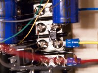
Not to be redundant but is the a connection between pin 1 and pin 5 of opti- coupler?
No. Please see picture from last post. The 4N37 is upside down, with Pins 2 and 4 connected only.
I think NP's schematic from BA2015 shows a connection between 1 and 5 - I'm sorry if I missed a change in that schematic
I think NP's schematic from BA2015 shows a connection between 1 and 5 - I'm sorry if I missed a change in that schematic
Generg pointed out the error on NP's schematic. It's on page 14, post #137.
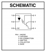
4n37 🙂
Yes, Sir - this is the exact one I used.
Next I am going to retrace all connections and make sure I did not make any stupid mistakes.
Attachments
Thanks Sir Generg we need 4N37 wiring clarifications.
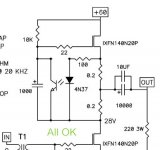
Schematic corrected now all is OK on the righ picture.
Cool
Schematic corrected now all is OK on the righ picture.
Cool
Attachments
Last edited:
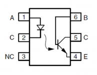
in the right picture is the fault again, no connection from the collector to the anode of the LED diode is right!
in the right picture is the fault again, no connection from the collector to the anode of the LED diode is right!
Thanks again Generg 🙂
Gerd's corrected pdf should be at audiohobby.com now as well. Let me know if it's not coming through.
🙂
http://www.audiohobby.com/download/baf-slides-nelson-pass/
🙂
http://www.audiohobby.com/download/baf-slides-nelson-pass/
Last edited:
Gerd's corrected pdf should be at audiohobby.com now as well. Let me know if it's not coming through.
🙂
BAF Slides Nelson Pass | Audiohobby.com
It´s coming perfectly dear Uncle 😀
Thanks and best regards
Yes, Sir - this is the exact one I used.
Next I am going to retrace all connections and make sure I did not make any stupid mistakes.
Very nice to see you build it. Great work.
Be patient, you'll find the problem.
I might check your photos later if you are still not having any luck.
OK - I get the 30V. I see 28V on the schematic also.
But I am not getting 30V at either side of the 2 0R2's. Even more strange:
1. Varying the bias from +4.7 with the probe at the 0R2 results in NO change - it measures 55.5VDC.
2. Varying the rail from +60 to +30 shows 25.7VDC.
soundhappy, generg.
Please see picture of 4N37. It's upside down, and floats above the terminal block. The schematic was wrong but I connected it correctly, I think!
It's not easy to tell the orientation of the device but Only 4 pins should be electrically connected
Last edited:
- Status
- Not open for further replies.
- Home
- Amplifiers
- Pass Labs
- BAF 2015 Coverage