ci11
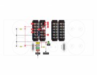
Am I missing the 100 ohm resistor that is between the photo coupler and the .2ohm resistor?
Thanks
Bob
Hi Bob,
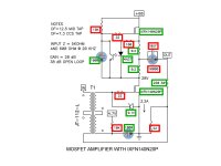
You are RIGHT - join the team of "What's wrong with this picture" finders. Attached please find rev2 of image showing missing 100R from S1/0R2 junction to the anode of the 4N37.
My sincere thanks.
Attachments
A word of gratitude to all those who contribute to this fine forum, for their ideas and tireless assistance to those who need help - like me.
And a very special thank you to Mr. Pass whose genius and generosity is helping so many reach farther than they ever dream possible.
Thank you to you all, and Happy 2016!
And a very special thank you to Mr. Pass whose genius and generosity is helping so many reach farther than they ever dream possible.
Thank you to you all, and Happy 2016!
Ditto 😀😀😀😀😀😀😀😀
A word of gratitude to all those who contribute to this fine forum, for their ideas and tireless assistance to those who need help - like me.
And a very special thank you to Mr. Pass whose genius and generosity is helping so many reach farther than they ever dream possible.
Thank you to you all, and Happy 2016!
A word of gratitude to all those who contribute to this fine forum....And a very special thank you to Mr. Pass whose genius and generosity is helping so many reach farther than they ever dream possible.
Thank you to you all, and Happy 2016!
Thank you too and Happy New Year 2016 to Papa 😎 and uncle Mike with all Diyers Team on forum and lot of joy from new amplifier's
 😀
😀
Last edited:
Bytheway, is there any aspects of power in the resistors exept these 0.2 ohms ?
looks like ordinary lowpower 0,5 -1watt will work.
/ Happy new year and so !
looks like ordinary lowpower 0,5 -1watt will work.
/ Happy new year and so !
Hello. Is there someone who has this amp up and running ?
Hi there,
I do not have it up and running yet but am on a path. Most parts are in except the heat sinks.
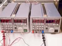
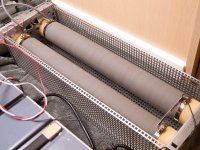
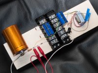
Attached are pictures of load-testing my serially connected bench supplies which produce +60V with 7.1A into a 1.5kW 8R6 current sink. The noise floor measured at 0.4mV or -68dB A-weighted which I think should do the job nicely. The bias voltage is also coming from a bench supply and it measures even lower.
Attachments
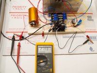
I got all the parts, hooked them all up, and checked all the connections and voltages:
Rail = +60V
Bias = +4.7V
I shorted the input to measure DC offset at the output, when I got 20+VDC!! Please see pictures.
What's going on? Where did I go wrong??
Rail = +60V
Bias = +4.7V
I shorted the input to measure DC offset at the output, when I got 20+VDC!! Please see pictures.
What's going on? Where did I go wrong??
Attachments
I got all the parts, hooked them all up, and checked all the connections and voltages:
Rail = +60V
Bias = +4.7V
I shorted the input to measure DC offset at the output, when I got 20+VDC!! Please see pictures.
What's going on? Where did I go wrong??
Bias is not exactly +4.7V.
You need to adjust the 4.7V voltage source until you get 30V at output.
It might be 4.75 V or 4.82V or 4.64V etc.
Make the adjustment and report back
did you expect some millivolt?
..... ?
I expected it to be different than 4.7V (ie not exactly 4.7V). It will depend on Id vs Vgs of the device, which is variable for every device.
I shorted the input to measure DC offset at the output, when I got 20+VDC!! Please see pictures.
Are you measuring from before the output cap? There's going to be a large DC voltage there, it's a single-rail supply.
Measure DC offset from downstream of the cap.
I expected it to be different than 4.7V (ie not exactly 4.7V). It will depend on Id vs Vgs of the device, which is variable for every device.
sorry Pico,
I did not mean you.
I had the impression like you that ci11 thought the offset voltage must be around zero.
But as you all said it is around half the rail voltage....
But may be I misunderstand ci11!
I expected it to be different than 4.7V (ie not exactly 4.7V). It will depend on Id vs Vgs of the device, which is variable for every device.
I varied the bias down to +3.5V and the DC is still there. In fact, the DC voltage appears to drop quite a bit, and if I wait 30 seconds, it would be around +10V. As soon as I turn the bench supplies off, the measured DC voltage flips from +ve to -ve.
Never saw this before!
Are you measuring from before the output cap? There's going to be a large DC voltage there, it's a single-rail supply.
Measure DC offset from downstream of the cap.
The +ve measurement is tapped right from the cap, and the -ve is tapped from the ground which is also connected to the source of the output mosfet.
sorry Pico,
I did not mean you.
I had the impression like you that ci11 thought the offset voltage must be around zero.
But as you all said it is around half the rail voltage....
But may be I misunderstand ci11!
The +4.7 is what's on the schematic, connected to a 10k. There was no +30 marked on the schematic that I have. Here is what I am working from:
Attachments
You need to get 30 V measuring between the output resistors and ground. Keep adjusting voltage source till you get 30V.
I did say these suckers are very sensitive to small changes in Vgs.
On the speaker side of cap you should have 0V otherwise there is something wrong with your cap.
I did say these suckers are very sensitive to small changes in Vgs.
On the speaker side of cap you should have 0V otherwise there is something wrong with your cap.
Forget 4.7V.
You need 30V at output.
I did say this needs fine adjustment for a reason. Adjust it till you get 30V
4.7V is Nelson's approximation.
You need 30V at output.
I did say this needs fine adjustment for a reason. Adjust it till you get 30V
4.7V is Nelson's approximation.
- Status
- Not open for further replies.
- Home
- Amplifiers
- Pass Labs
- BAF 2015 Coverage