Hi ci11,
When the layout like this is on internet it is something like being 'published'. Then it can make some one perplexed when he is using your layout. You know what I mean. I was like that.. 🙂
Now I see that's ready to go..!
Hi 2pD, do you think there will be any current between the gate and source? I had this ecperience with other 2Sk180.
Last edited:
Hi 2pD, do you think there will be any current between the gate and source? I had this ecperience with other 2Sk180.
Not with IXYS devices.
You mean current leaking through gate?
Not with IXYS devices.
You mean current leaking through gate?
Yes I found that with 2SK180. This delayed the bias settlement. We have CCS with optocoupler that will help in this circuit? I was asking just in case..
IXYS hockey pucks should be fine.
Thank you, that will make it easier for me. 🙂
In fact I've never seen a hocky puck, and it looks smaller than I thought..
Hi ci11,
When the layout like this is on internet it is something like being 'published'. Then it can make some one perplexed when he is using your layout. You know what I mean. I was like that.. 🙂
Now I see that's ready to go..!
Hi 2pD, do you think there will be any current between the gate and source? I had this ecperience with other 2Sk180.
Chul,
It's Papa's work, and I am lucky to be able to interpret it with his help and the help of 2pD checking over mistakes and misses. I have started the actual component placement so many more discussions with suppliers are needed and it may take some time.
Sounds like you're all good to go.
Thanks again for all your help.
Yes I found that with 2SK180. This delayed the bias settlement. We have CCS with optocoupler that will help in this circuit? I was asking just in case..
A 2SK180 can have leakage current of up to 100uA (or more), with a 10k bias resistor this can disturb your bias for up to 1V.
The IXYS datasheet leakage current max out at 100nA, a thousand times less than the 2SK180.
A 2SK180 can have leakage current of up to 100uA (or more), with a 10k bias resistor this can disturb your bias for up to 1V.
The IXYS datasheet leakage current max out at 100nA, a thousand times less than the 2SK180.
Hi Tim,
Yes I learned that the hard way 😀, and then tried self bias, then I checked all of them for matching. Now I think I am ready to go back to fixed bias.
I was worried about the leakage of this big IXFN part, but thank you for letting me know that the amount is small.
Last edited:
Since you have some 2SK180, maybe you can try the 2SK77B amp with 2SK180, instead of using the IXYS with Shade feedback 🙂
Tim, I also have some 2SK182ES and some THF51-S (impulsive purchase..😀) and like you said I'd like to try in this circuit without Shade feedback and with/without transformer.
About the leakage current of SIT's, I thought that a current limiting diode in series with 10K would help them stablize the current quicker, but I could not find this small current one. Or this coptocoupler may be used with 10K, using the 1.2V turn on of diode side? Just a thought, but may be possible.. 😕
About the leakage current of SIT's, I thought that a current limiting diode in series with 10K would help them stablize the current quicker, but I could not find this small current one. Or this coptocoupler may be used with 10K, using the 1.2V turn on of diode side? Just a thought, but may be possible.. 😕
Or you may consider a grid choke, low DC resistance so much less drift in bias, and high AC impedance so easy to drive by the source, main issue is that good ones are not cheap.
Or you may consider a grid choke, low DC resistance so much less drift in bias, and high AC impedance so easy to drive by the source, main issue is that good ones are not cheap.
Hey, that will be effective I am sure! I tried grid choke only in self bias circuit, from my experienc from tube SET... Thank you Tim! 🙂🙂
With additional guidance from Papa regarding the power supply and caveats, I made the decision to do my build using terminal blocks and a decentralized topology. The idea is to start with bench supplies then migrate to a PSU box, and keep the output devices and their heat sinks outboard as well, since the ones I chose are likely too big for a case.
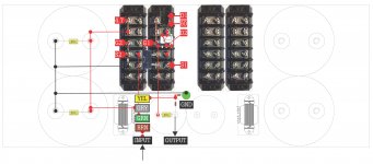
The bench supplies passed their load test this week but noise tests are still to be measured with a better instrument that is on its way. Components are mostly on hand with the heat sinks now on order. So it was time to do an actual component layout. I took a run at the logic flow a couple of weeks back and with the help of 2picoDumb and Chul, the results were posts earlier in this thread. Now with specific component on hand, I did a life-size layout to scale to find out if there are any space or logic conflicts. A few notes on the picture, it's big so details can be seen, the PSU and output devices are not included, the 2 big cans on each side are DC Link film caps paralleled for the FB loop, and the small can is the output coupling cap.
Your generous feedback, comments and corrections are much appreciated!!
Attachments
Last edited:
Thanks for posting this but if you don't mind
Could you say more about the DC link caps - Value?
Do they replace the 1000µF electrolytic?
I will continue to work my way through your set-up. Great learning experience
Best
Bob
Could you say more about the DC link caps - Value?
Do they replace the 1000µF electrolytic?
I will continue to work my way through your set-up. Great learning experience
Best
Bob
Thanks for posting this but if you don't mind
Could you say more about the DC link caps - Value?
Do they replace the 1000µF electrolytic?
I will continue to work my way through your set-up. Great learning experience
Best
Bob
Hi Bob,
Thanks for the kind words. Papa and members all helped me to get this far, and hopefully my adventure is helpful to those who want to go this way as well.
As for the DC Link caps, yes, the 2 490µF paralleled are in place of the 1000µF in the schematic. They are CDE 947C's rated at 800V and 70A so way over the top for this application. They are also big (90x120) and pricy (@$50) but I am very curious as to what they will do. There had been a flurry of comments on a few forums on their use but nothing declared them definitively as the holy grail or a giant waste of money. Given the simplicity and nature of this circuit, if it makes a difference anywhere, it will here.
Really interesting
I was thinking of using Elnas and bypassing with 10uF Obbligatos or some motor run caps which I have. Experimentation 😀😀😀😀
Best
I was thinking of using Elnas and bypassing with 10uF Obbligatos or some motor run caps which I have. Experimentation 😀😀😀😀
Best
Really interesting
I was thinking of using Elnas and bypassing with 10uF Obbligatos or some motor run caps which I have. Experimentation 😀😀😀😀
Best
That will also work.
Really interesting
I was thinking of using Elnas and bypassing with 10uF Obbligatos or some motor run caps which I have. Experimentation 😀😀😀😀
Best
I think 2pD is right - anything else within reason will work. I've had good luck wiht SILMIC II's too, but no experience yet with Obbligatos. My plan for bypass is a 10µF Epcos flim and 10nF polystyrene although in this same position in the Nakamichi PA7, I also found the Mundorf eCap excellent.
- Status
- Not open for further replies.
- Home
- Amplifiers
- Pass Labs
- BAF 2015 Coverage