Your sims helped a lot also - thank you!
I've been trying to improve my skills on Eagle and Design Spark PCB. Not so user friendly and fairly tedious but getting there.
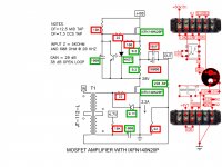
Are you planning to write an article on the IXFN140N20P amp?
I suppose I'll get round to it (particularly busy at the moment) but pretty
much everything you need is on that schematic.
I think 6L6 is going to put something together for the DIY.
The only caveat is that circuit as shown needs a low impedance DC coupled
drive.
😎
...The only caveat is that circuit as shown needs a low impedance DC coupled drive...😎
Thank you, Mr. Pass!
For the PSU, I was thinking about one of 2 ways - building half of the CSX 1 PSU you described in the VFET Pt 1 article, or just connecting my bench PSU's in the same way you did as shown at the end of that article - mine are all at <1mV.
Parts cost and some fan noise aside, which approach is the better choice?
I would start with the bench supplies and go from there.
😎
My bench supplies did not publish an output impedance but my guess is not more than 0.5 mOhm in voltage mode. They also appear to be direct coupled from the schematic. For regulation, they have remote sensing and can hold to <0.01% in CV, and <0.02% in CC modes. Noise is 1mV and 20mA RMS. They have been pretty good for the bench.
So that's where I will start, when the heat sinks eventually get here. Thanks again, Mr Pass!

Found 1 error so far.
Bottom of transformer on input side does not goes directly to ground on your layout. This does not agree with schematic.
It should connect between the 220 Ohm and 22 Ohm resistor.
Bottom of transformer on input side does not goes directly to ground on your layout. This does not agree with schematic.
It should connect between the 220 Ohm and 22 Ohm resistor.
Last edited:
4.7V bias has to go through the 10K resistor first..
(-) leg of upper 1000uF cap is not connected?
I am preparing turret boards, soemthing like in the old guitar amp hard wiring. 🙄
(-) leg of upper 1000uF cap is not connected?
I am preparing turret boards, soemthing like in the old guitar amp hard wiring. 🙄
Last edited:
Gentlemen,
Thank you for your input - I knew my brains needed help!
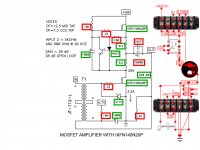
2pD: you are right, and the attached picture reflects the change.
Chul: 4V7 goes "down" on the strip through the 10K attached to the bottom then "up" through the 1000µF, whose -ve is attached on the next strip, then goes to ground. Sorry these was no -ve sign shown on the 1000µF.
Hope this does it....thanks again, gentlemen!
Thank you for your input - I knew my brains needed help!
2pD: you are right, and the attached picture reflects the change.
Chul: 4V7 goes "down" on the strip through the 10K attached to the bottom then "up" through the 1000µF, whose -ve is attached on the next strip, then goes to ground. Sorry these was no -ve sign shown on the 1000µF.
Hope this does it....thanks again, gentlemen!
Attachments

If you look at 4V7 on your layout. it by-passes 10k resistor to bottom of transformer.
That needs to be corrected on your layout.
That needs to be corrected on your layout.
Last edited:
If you look at 4V7 on your layout. it by-passes 10k resistor to bottom of transformer.
That needs to be corrected on your layout.
You are right again! Here it is.
Attachments

Bottom of diode and transister on 4n37 on your layout are not electrically connected to each other.
Needs correction.
Needs correction.
Bottom of diode and transister on 4n37 on your layout are not electrically connected to each other.
Needs correction.
It's now downright embarrassing - I should stick with software.
Attachments
I've checked it one more time. Looks good.
Regarding 4V7 if you are using lab powersupply, you need to be able to adjust in 10mV intervals to get the adjustment you need. If you're supply doesn't have fine adjustment you might need to build either voltage reference circuits posted earlier.
Either way, you may as well start with what you have.
...Regarding 4V7 if you are using lab powersupply, you need to be able to adjust in 10mV intervals to get the adjustment you need. ....
2pD
Thanks for the reassurance on the routing.
My bench supply for the 4V7 has fine adjustability in 1mV steps, and deviation of 0.5mV. With its low ripple of <1mV and remote sensing, I thought it would be a good candidate even if it may be a long run between the supply and the amp. With papa having weighed in suggesting bench supplies as a good first step, I'm going for it. Otherwise, I would have adopted your LT1431 or Zener regulator idea.
Thanks again for your look over, I hope the terminal block approach provides an interesting alternative to all those who plan to build this fabulous amp, and perhaps even experiment with creative case configurations beyond a boxy 4U/5U.
Last edited:
Sounds like you're all good to go.2pD
Thanks for the reassurance on the routing.
My bench supply for the 4V7 has fine adjustability in 1mV steps, and deviation of 0.5mV. With its low ripple of <1mV and remote sensing, I thought it would be a good candidate even if it may be a long run between the supply and the amp.
- Status
- Not open for further replies.
- Home
- Amplifiers
- Pass Labs
- BAF 2015 Coverage