
If this is a hazard that can cause damage, are there warnings for clueless folks like myself? I would not have considered the order I turn on the components to be a hazard to he mitigated. I might need to put some red labels on my equipment now as a reminder. It's a good lesson to share and I really appreciate that you have Russell!
I'm going to ground positive as well for startup. Funny thing, while obviously undid it, dont remember when I removed the positive ground.
I guess after fire up and all measuring well. I didnt note doing it for some reason
I guess after fire up and all measuring well. I didnt note doing it for some reason
We'll see. I dont know what "chops" I have, but I put it together first time, hoping I caught all, doubting same. I have pretty much decided to build another of these, but may complete M25 boards that are built in a box first and see if this current limiting deal works out. I have no idea what kind of voltage was on outputs when this occurred. One member commented he got 40 volts on his....maybe I should install DC blockers I have boards for. The speakers I was playing at the time were the XSD speakers from X. There are eight woofers per side, 4 push pull pairs. The drivers are not horribly expensive, I think 16 for both sides were under 250 if I recall. They seem just fine. Pretty good pop.Hey, we all screw up, I think I must have once or twice, obviously this does not apply to ZM! Fortunately you have the chops to fix it, think if you had to send it somewhere for service!
I think that people often worry needlessly about damaging speakers, not to say that I haven't done it myself, think Telarc 1812 Overture. If those cannons don't destroy your speakers many of the pops, bangs and booms that we inadvertently cause can be handled, in my experience.Pretty good pop.
The difference is, those transients are not a massive whallop of DC. It isn't the pop itself, it's the DC which roasts voice coils.
Of course, there are definite no nos, but often people freak when a loud something goes thru the system, like plugging in an RCA to an amp that is on and connected to speakers, not that I've ever done that 🙄 Good practices are really best followed, laziness is the enemy of success!
177 mV, offset .2 mV getting up to heat. I think this channel is good, over to the other one. Heatsink low 40's C. Think I will let it cook a while.
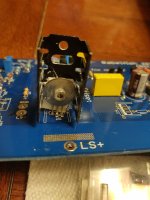
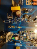
2nd channel not so good. When variac got to about 70 volts, whisp of smoke. Can't really tell where it came from, possibly R24 looks possibly tanned, maybe.
Started turning variac up, definitely R24. What now? Disassemble and test/replace same parts?
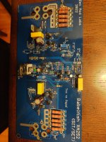
I was super careful not to mix up Q1 and Q2, but you know how that goes. I replaced all the suggested parts, just like in other channel. Q1,Q2, T6, R19, R21, R22 and R24.
I assume next step is tear down? Or anything else to check first?
Russell
Started turning variac up, definitely R24. What now? Disassemble and test/replace same parts?
I was super careful not to mix up Q1 and Q2, but you know how that goes. I replaced all the suggested parts, just like in other channel. Q1,Q2, T6, R19, R21, R22 and R24.
I assume next step is tear down? Or anything else to check first?
Russell
I assume next step is tear down?
well, you have DMM and SuperGizmo tester
if R24 was toasted, any surrounding part was in danger of overcurrent
parts are cheap, work is cumbersome, so better to replace more than less, as it happened on that channel
no need for so big washers on BD transistors; and - with smaller washers you can see numbers on them
or - take red sharpie and paint red pins of BD139, so you'll see red pins even when soldered in place, as confirmation that red is in positive rail side
Could something like this work for the base resistors ?I'm thinking how to implement current limiting in push-pull emiter follower buffer stage in XA252, but still didn't found definitive solution
Front end on first, then power amp, reverse got power down.If this is a hazard that can cause damage, are there warnings for clueless folks like myself? I would not have considered the order I turn on the components to be a hazard to he mitigated. I might need to put some red labels on my equipment now as a reminder. It's a good lesson to share and I really appreciate that you have Russell!
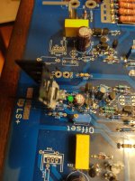
There are a couple of tiny items, smd caps maybe, and parts right by where transistor sandwich 6 legs go into board. Seems solder slightly disturbed from nearby removal/reinstall of sandwich. Could I have messed them up causing this? I will post pics of board as soon as parts removed.
If all parts are new, can't figure why R24 went. Would reversal of positions of Q1 and Q2 do this? I checked and double checked, Q1= BD 139, Q2 = BD 140.....but you know how it goes...first channel perfect.
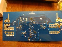
Board disassembly after work today, and check parts. The resistor was just starting to smoke, backed off variac, none others disturbed. Visually anyway. All parts will be replaced. Again!
Russellc
If all parts are new, can't figure why R24 went. Would reversal of positions of Q1 and Q2 do this? I checked and double checked, Q1= BD 139, Q2 = BD 140.....but you know how it goes...first channel perfect.
Board disassembly after work today, and check parts. The resistor was just starting to smoke, backed off variac, none others disturbed. Visually anyway. All parts will be replaced. Again!
Russellc
Last edited:
I noticed that the Stasis 2,3 has 470r base stoppers in the old driver stage, just as a datapoint...
Would a local current limiter on the VAS help in these transient overdrive situations? (I'm probably beyond my pay grade here..)
Would a local current limiter on the VAS help in these transient overdrive situations? (I'm probably beyond my pay grade here..)
Russell, see if you can cleanup that whole area. R21 solder pad looks like it could be touching adjacent c6. BD sandwich missing mica? I got a Hakka desoldering tool when I had my issues, and it made the removal of components so much easier and cleaner. Also, I was able to test probably 95% of the components installed, so using your dmm and super gizmo tester should find the problem.
@william2001
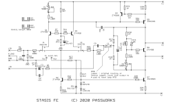
Study Papa's New Stasis FE - there is limiting cell (Q4) where it needs to be
When I asked Pa about that detail, his answer was pretty much like "prevention of disaster in case of..."
Now you know and I know ........
Though, ZM need to build more cleverness to implement any sort of no-invasive limiting zingy in existing emiter follower stage in XA252
For now, I devised next gen, having 2 LEDs in series as base spreader, allowing use of 2*91R in between emiters, at least partially decreasing Poof possibility
that enables next step - no other way than adding few smd bjts and few smd resistors, monitoring current through each 91R emiter resistor, and clamping BD bases when current goes to - say 40mA
attached Papa's Stasis FE
Clever Pa.......
Attachments
- Home
- Amplifiers
- Pass Labs
- Babelfish XA252 / Babelfish XA252 SIT / Babelfish XA252 SET