@Mikerodrig27 I think one inductor is gracious plenty per rail. All my sims (I am NO expert) showed that placing the inductor "first" had the best ripple reduction. However, I'd run some sims yourself with your setup... it's fun. I used the Hammond 159ZJ that a lot of folks use. I copied shamelessly.
The link for the resistors took me to several, but I got the gist. See page 2 of the data sheet for expected temp rise at a given load factor. Then look back to page 1 to see how the rating drops with temp rise. I'm hinting toward using at least two in parallel. I'm not sure if it's strictly necessary. I haven't done calcs for your PSU, but give it some thought...
Can't wait to hear how those DC link caps work out! I've seen them mentioned a few times, but I've never seen them in a build.
Nah... not too off topic.... at least not for a ZM thread.
You are correct, it is Antek transformer. I just wanted to make sure my assignment of bridge connections 1,2,3 and 4 were the same as the 1,2,3 and 4 of the data sheet locations on actual device.Looks fine to me... but, as always... particularly with me... extra set of eyes besides mine is good. Also... depending on the toroid you're using... it's unlikely that it will be the red and black going to the rectifiers... maybe the green and blue?? Juuuuuuuust in case.... anyway. The secondaries. Not the primaries... of an Antek is where I'm going with that. 🙂
Russellc
You are right. So long as we mention the inductor, it is on topic. I see the PL power supply using one single resistor per rail up against the caps. It looks like a 3w which is why I thought maybe a 5w and vent holes would be more than enough.
I started the simulation on PSUD. I will play with some values tonight and see what I get. I am still pretty fresh with PSUD but at least it is a simple program. Looking at Randy's Aleph BOM's, they call for a single 5w resistor of .22 and .33 per rail serving a Aleph 2 monoblock. So lots of current. From the sounds of it, these should do alright. I will check the simulation regardless.
I started the simulation on PSUD. I will play with some values tonight and see what I get. I am still pretty fresh with PSUD but at least it is a simple program. Looking at Randy's Aleph BOM's, they call for a single 5w resistor of .22 and .33 per rail serving a Aleph 2 monoblock. So lots of current. From the sounds of it, these should do alright. I will check the simulation regardless.
Thanks for confirmation, when I start flipping and "converting" diagrams, mistakes abound.1. +
2. AC
3. -
4. AC

Back to wiring.
Russellc
Not sure which PSU schematic, but that would be odd (to me).You are right. So long as we mention the inductor, it is on topic. I see the PL power supply using one single resistor per rail up against the caps. It looks like a 3w which is why I thought maybe a 5w and vent holes would be more than enough.
Awesome. It's fun to fool withI started the simulation on PSUD. I will play with some values tonight and see what I get. I am still pretty fresh with PSUD but at least it is a simple program.
Best to be sure we're looking at the same thing. Attached is the guide I have for the 2s.Looking at Randy's Aleph BOM's, they call for a single 5w resistor of .22 and .33 per rail serving a Aleph 2 monoblock. So lots of current. From the sounds of it, these should do alright. I will check the simulation regardless.
Page 18 is the schematic for Randy's V8. The filter resistors are the parallel pairs. R1-8. R9 and R10 are the bleeder resistors. That's also how the PCB is designed. I can't say for certain re: Randy's other PCBs.
The Sims can show you the power through the resistors... yes.
Cool. 😎 I had just noticed in your drawing that you had labeled the AC wiring connected to the rectifiers as red and black. That's the primary side of an Antek 😉 Unless you do your own wiring, the side you will connect to the rectifiers will be blue and green.You are correct, it is Antek transformer.
Attachments

Okay, since we are talking about Aleph 2 stuff, it is important that I say the word "Inductor". Now that is out of the way, Highlighted on the top left "0R22-0R33" is the filter resistor for the A2. I really like these big radial resistors less parts to solder, order etc. the resistors on the A2's I built were quite comfortable doing their job.

Here is a screenshot from a video on youtube where Wayne talks about their amps. This is the medium sized chassis I believe. So XA100 = lots of current. You can see, CCCRCCC with that resistor being the filter resistor. Now these are X amps so filtering isn't as critical so I made mine have two stages of filtering. I had to look hard to find out what part the resistor was as I like the idea of it being so raised. Also, you can figure it is going to be a reliable part because Pass's amps last until the end time due to great part selection and their terrific engineering (as we know 🙂 )

I will report back with some PSUD stuff when I get a minute to mess with it.
Here is a screenshot from a video on youtube where Wayne talks about their amps. This is the medium sized chassis I believe. So XA100 = lots of current. You can see, CCCRCCC with that resistor being the filter resistor. Now these are X amps so filtering isn't as critical so I made mine have two stages of filtering. I had to look hard to find out what part the resistor was as I like the idea of it being so raised. Also, you can figure it is going to be a reliable part because Pass's amps last until the end time due to great part selection and their terrific engineering (as we know 🙂 )
I will report back with some PSUD stuff when I get a minute to mess with it.
Yes, I was copying a diagram and carried colors over, was only concerned if I had labeled 1-4 on the bridge correctly! All my amps except one use anteks.Not sure which PSU schematic, but that would be odd (to me).
Awesome. It's fun to fool with
Best to be sure we're looking at the same thing. Attached is the guide I have for the 2s.
Page 18 is the schematic for Randy's V8. The filter resistors are the parallel pairs. R1-8. R9 and R10 are the bleeder resistors. That's also how the PCB is designed. I can't say for certain re: Randy's other PCBs.
The Sims can show you the power through the resistors... yes.
Cool. 😎 I had just noticed in your drawing that you had labeled the AC wiring connected to the rectifiers as red and black. That's the primary side of an Antek 😉 Unless you do your own wiring, the side you will connect to the rectifiers will be blue and green.
Thanks,
Russellc
Emphasis added is mine - maybe we're saying the same thing... but different ways...Looking at Randy's Aleph BOM's, they call for a single 5w resistor of .22 and .33 per rail serving a Aleph 2 monoblock.
Maybe I should start over. What I'm trying to say is that if you don't use the inductors, that it may be nice to put in pads to have two resistors in parallel instead of just one.
The way I would phrase is that there are 4 per rail. See below.
I don't doubt your build. However, I don't know what PSU you built or the schematic you used for your Aleph 2.Now that is out of the way, Highlighted on the top left "0R22-0R33" is the filter resistor for the A2. I really like these big radial resistors less parts to solder, order etc. the resistors on the A2's I built were quite comfortable doing their job.
View attachment 1233720
That is the BoM for one PSU, yes. Agreed. Now, look at the schematic on Page 18.
Note in the schematic that R1 is in parallel with R2. R3 is in parallel with R4. R5 is in parallel with R6. R7 is in parallel with R8. 4 pairs of paralleled 5W rated resistors per PSU. So... you get the rough equivalent of a 10W resistor for each pair. Why... b/c it would be very likely that if one were to put a single 5W resistor of equal value to the two in parallel that it would get very, very warm.
I can't see that resistor value or the traces, so I don't know what the function might be. Apologies. I fully trust you, but that doesn't help me too much.Here is a screenshot from a video on youtube where Wayne talks about their amps. This is the medium sized chassis I believe. So XA100 = lots of current. You can see, CCCRCCC with that resistor being the filter resistor. Now these are X amps so filtering isn't as critical so I made mine have two stages of filtering. I had to look hard to find out what part the resistor was as I like the idea of it being so raised. Also, you can figure it is going to be a reliable part because Pass's amps last until the end time due to great part selection and their terrific engineering (as we know 🙂 )
View attachment 1233722
Awesome. I think you'll dig it.I will report back with some PSUD stuff when I get a minute to mess with it.
Hmm, you have a point, the A2 has two resistors in parallel. Funny, I am sure I knew that when I put them together a while back but It has been a while...
Okay, so using some simple ohms law, let's assume 2 amps going through a single rail. With a resistor value of 0.1ohms. I am seeing .4 watts, .2v drop in that extreme situation. Looking at PSUD, my thoughts are sorta verified. Going from C1 to C2 shows a voltage drop of 0.132v accross the resistor. So (0.132/0.200) 0.4 =0.66 x 0.4 watts = 0.264 watts. Now I am not the best at math so I wouldn't be surprised if I am doing something wrong but it looks to me like a 3-watt resistor can handle around 10x as much power as needed. Of course, dissipating 3 watts would make it really hot. So a 5w resistor in my situation should be able to handle quite of current especially since we are dealing with one channel.
I suppose another thing to keep in mind is the aleph 2 makes a lot of current and the parallel resistors are dissapating for both sides... So I kind of have the equivalant of the two resistors in parallel. In other words, the A2 has 8x5w resistors and my power supply has 8x 5w resistors 😀

With that being said, now the "why not" factor is kicking in... Sign. Let me know if you think I am driving into a ditch or if I am on course.
Okay, so using some simple ohms law, let's assume 2 amps going through a single rail. With a resistor value of 0.1ohms. I am seeing .4 watts, .2v drop in that extreme situation. Looking at PSUD, my thoughts are sorta verified. Going from C1 to C2 shows a voltage drop of 0.132v accross the resistor. So (0.132/0.200) 0.4 =0.66 x 0.4 watts = 0.264 watts. Now I am not the best at math so I wouldn't be surprised if I am doing something wrong but it looks to me like a 3-watt resistor can handle around 10x as much power as needed. Of course, dissipating 3 watts would make it really hot. So a 5w resistor in my situation should be able to handle quite of current especially since we are dealing with one channel.
I suppose another thing to keep in mind is the aleph 2 makes a lot of current and the parallel resistors are dissapating for both sides... So I kind of have the equivalant of the two resistors in parallel. In other words, the A2 has 8x5w resistors and my power supply has 8x 5w resistors 😀
With that being said, now the "why not" factor is kicking in... Sign. Let me know if you think I am driving into a ditch or if I am on course.
Nice!
I absolutely don't/didn't think you are/were driving into a ditch. IMO, it's a kick a$$ design / idea. If you're considering using those boards for other things....
P (power dissipated) = I^2 (current) × R (resistance)
Why did I underline and bold that part? B/C I still don't know if you're running dual mono (if you mentioned, apologies) and/or if you're considering using those boards for anything else that may be a power thirsty monster. The dissipation rises at the square of the current. Example... if you wanted to use it for let's say... an amp at Iq of 2A5 per channel, and it's not dual mono....
So... I like adding a set of pads... even if they're never used. It's surprising (to me) how quickly the temp rises with the load, and it makes your already cool idea a bit more versatile, IMO.
Mainly... enjoy!
Hi,
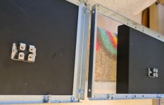
some progress: pucks are mounted.
To avoid making a mess with the goop, after dry-mounting the pucks, I covered their outlines with self-adhesive tape so that the squeezed-out residue can be easily removed. And shortly afterwards I also invented the wheel

some progress: pucks are mounted.
To avoid making a mess with the goop, after dry-mounting the pucks, I covered their outlines with self-adhesive tape so that the squeezed-out residue can be easily removed. And shortly afterwards I also invented the wheel
Attachments
God first invented a Wheel
Right after, Buddha came with second and last best invention - wing car window
what's wrong with goop around, it's perfect to attract wandering dust particles .........
edit - you didn't forgot split washers?
Right after, Buddha came with second and last best invention - wing car window
what's wrong with goop around, it's perfect to attract wandering dust particles .........
edit - you didn't forgot split washers?
I think your idea of adding pads for parallel resistors is a great practical idea. I have just simply run out of room. With the width of the chassis that I am using, If I added them, the PCB would be pretty much touching the heatsinks. 😬
One transformer is powering two cap banks.
One transformer is powering two cap banks.
God first invented a Wheel
Right after, Buddha came with second and last best invention - wing car window
what's wrong with goop around, it's perfect to attract wandering dust particles .........
edit - you didn't forgot split washers?
No, there are split washers 👍
Little progress: grounding "bus" drilled, mounted.
No, the caps are not mismatched

No, the caps are not mismatched
Mightiness,
maybe I will use motor run caps as the last cap in the rail - would 50 or 60 uF / 450vac from TDK be ok?
Thanks in advance.
maybe I will use motor run caps as the last cap in the rail - would 50 or 60 uF / 450vac from TDK be ok?
Thanks in advance.
you can produce another heatsinkless case per channel, fill it with motor-runs and connect that bank with amp through umbilical
if (edit: ) unnamed Brit Factory can sell it to Audiophools, I can too

(edit was simply - why Mighty ZM should even mention them)

if (edit: ) unnamed Brit Factory can sell it to Audiophools, I can too
(edit was simply - why Mighty ZM should even mention them)
I am using an Antek transformer as it is on hand, and I will start with it. Intended to do two transformers, and HA boards. For now I will use this Antek and one of my Teabag power supply boards with the same capacitors. Back to the transformer. It is Antek AN-6428, 600VA, 28 + 28, but it also has two other outputs !8 volt and a 12volt which will not be used. How should these unused out put leads be dressed? cut short and capped off?
Or should I not putz with it and get two Antek 300VA 28 + 28 volt?
Outputs:
1. 28v
2. 28v
3. 18v
4.12v
Thanks,
Russellc
Or should I not putz with it and get two Antek 300VA 28 + 28 volt?
Outputs:
1. 28v
2. 28v
3. 18v
4.12v
Thanks,
Russellc
of course that dual mono approach ( each channel having own dedicated PSU) is better, and this amp is worthy of best anything you can think of
so, you made your choice here ..... I can mock ya or not, but only you can measure your wallet efforts vs. wide of your green
unused secondaries - do not cut them (blasphemy) , just isolate each wire end, then heatshrink them together and neatly tuck around Donut
so, you made your choice here ..... I can mock ya or not, but only you can measure your wallet efforts vs. wide of your green
unused secondaries - do not cut them (blasphemy) , just isolate each wire end, then heatshrink them together and neatly tuck around Donut
- Home
- Amplifiers
- Pass Labs
- Babelfish XA252 / Babelfish XA252 SIT / Babelfish XA252 SET