I will have an "approval" photo for "better safe than sorry" shortly. Looking at the data sheet for my fancy puck rectifiers, and data sheet for "regular" block rectifiers, I believe I have the correct wiring setup!
Guess I got spoiled by regular block style having cut corner marking. Be back in a quick.
That and drilling holes to connect woofer pairs in XSD speaker project are on today's get done as much as possible list.
Russellc
Guess I got spoiled by regular block style having cut corner marking. Be back in a quick.
That and drilling holes to connect woofer pairs in XSD speaker project are on today's get done as much as possible list.
Russellc
I think @Mikerodrig27 covered the balanced / differential input part. I don't think Plott is building his monoblocks to output a differential signal ... which is what I think you're wondering.
Agree. That's what I see in the pic. Doesn't mean two channels per chassis. Only @Plott would know that plan.
tl;dr - The monoblocks will likely be SE in SE out. Bal in SE out (incorrect, but hopefully illustrative terms). You are correct, if he were doing "balanced" out, there would need to be two amp boards per channel.

Missed this explanation. Extra hard head here folks!Mike,
looking at the input stage I think (and ZM says too) it has a real balanced input, and can also be used as SE, when neg. input is grounded. But ZM will surely correct us.
Yes. Yes it sure would! Thanks for the explanation 😃For the front stage to be balanced, wouldn't it have to put out a +phase and -phase into the output stage? It looks like one trace going from the output of Q1 and Q2 into the output stage. Maybe I am wrong too and Zen Mods tricks go right over my head. lol
Well, I'm building two monoblocks and as ZM wrote, the amp has balanced and SE inputs.

From what I see, he has one standard channel going into each monoblock. A fun way of going about it.Well, I am confused about two channels in each mono block then. Not for now anyway, I haven't got the "regular" version running yet!
Russellc
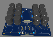
Thanks! The pucks will be mounted directly to the heatsinks and connected with very short wires to the boards.
The now open areas will be covered with aluminum plates (left, right) and with the rear/front/top panels.
Motor run caps - I don't know, perhaps.
And there will be some needle thingie on the front to display the bias current status 🙂
The now open areas will be covered with aluminum plates (left, right) and with the rear/front/top panels.
Motor run caps - I don't know, perhaps.
And there will be some needle thingie on the front to display the bias current status 🙂
Pretty cool! Standoff I assume. I have gotten standoffs on Ebay that are ~$3 or longer for a good price. i am working on a power supply PCB that integrates films for my next project. I want to see what all of the fuss is about 🙂
Thingiess with needles... Crochet? Going to be a nice piece.
Thingiess with needles... Crochet? Going to be a nice piece.
Yes, standoff for the pcb, I have two candidates, one strong plastic L-shaped, and one usual metal standoff.
No crochet Just some heavily modified needle panel meters.
To your PSU pcb - CRC, or a more exotic CLC, CLCRC, whatever?
No crochet
Just some heavily modified needle panel meters.To your PSU pcb - CRC, or a more exotic CLC, CLCRC, whatever?
Very cool. I am sure either will work.
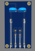
It is going to be a dual'ish mono power supply. Let me know if the below makes sense.
One transformer goes to one set of rectifiers which sends the V+ and V- out to two sets of cap banks. The 2nd resistor in each of the CRCRCCF banks have large enough pads to hook up an inductor to so it could be CRCLCCF. The F stands for a film cap.
Left Channel V-OUT- FCCRCRC - Rectifiers - CRCRCCF - Right channel V-OUT
There is a spot in the center of the caps for a soft start which will either be a CL-60 or the DIYaudioStore one. I have both drawn up. The mains out of the soft start drop down through the hole in the PCB then underneath to the transformer.
It is very loosely based off of the Pass labs PS using 8 35mm caps rather than 12 25mm caps per side and with films as well as secondary snubbers.
Attachments
Nice!!!! Few questions...
Did you sim the inductor as a sub for both "first" and "second" R? Do you have a preference? Maybe put a set of pads next to each for versatility?
Are the Pi resistor pads big enough for power rating / size resistors you want? From that angle, I only see one pad for each. Unless they're sized for big ol' honkers (even with 35mm caps for scale, it's tough to tell)... either way... you may want some pads for a few in parallel, or they're likely going to be WARM right up against your caps.
Here is pic from data sheet:I will have an "approval" photo for "better safe than sorry" shortly. Looking at the data sheet for my fancy puck rectifiers, and data sheet for "regular" block rectifiers, I believe I have the correct wiring setup!
Guess I got spoiled by regular block style having cut corner marking. Be back in a quick.
That and drilling holes to connect woofer pairs in XSD speaker project are on today's get done as much as possible list.
Russellc
Attachments
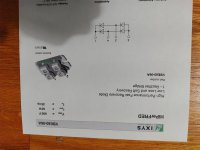
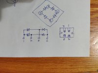
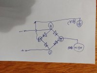
Hopefully, figured correctly for least smoke out put! Nutz, everyone upside down.
Thanks,
Russellc
Thanks,
Russellc
Looks fine to me... but, as always... particularly with me... extra set of eyes besides mine is good. Also... depending on the toroid you're using... it's unlikely that it will be the red and black going to the rectifiers... maybe the green and blue?? Juuuuuuuust in case.... anyway. The secondaries. Not the primaries... of an Antek is where I'm going with that. 🙂
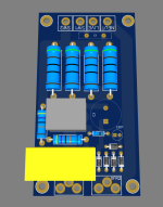
I have not. I simulated just the basic CRCRCC as that is what I will use first. Do you have a particular inductor that you use in your setup? I actually need to check the wire gauge but I figured 1.8mm should be a large enough hole for inductor leads. For the resistors, I am going to use these. So the filtering will be light. Probably .05-.1 for each resistor hence two stages. You can see the holes around the resistors for airflow.Nice!!!! Few questions...
Did you sim the inductor as a sub for both "first" and "second" R? Do you have a preference? Maybe put a set of pads next to each for versatility?
Are the Pi resistor pads big enough for power rating / size resistors you want? From that angle, I only see one pad for each. Unless they're sized for big ol' honkers (even with 35mm caps for scale, it's tough to tell)... either way... you may want some pads for a few in parallel, or they're likely going to be WARM right up against your caps.
The films will be these (C4AQLBW5700A3LK)
The EL 35mm caps will be these
So for around a couple hundred dollars (with resistor filtering) , it will be a very solid power supply.
I should sim CLCLCC and see what it looks like. Only that would be 8 inductors 😳. I do havehole locations to add a platform for inductors if I want to.
Here is the spacing around the resistors:
I suppose this is getting pretty off-topic now. 😬
- Home
- Amplifiers
- Pass Labs
- Babelfish XA252 / Babelfish XA252 SIT / Babelfish XA252 SET