Q1 (BD139) was bad. I checked it earlier and it seemed fine but apparently not. Luckily, ZM included 4 in the kit so I had a spare. 🙂 Currently listening to it biased at about 185mV with <5mV offset.
Last edited:

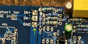
When testing outside the amp, you still want to ground IN+ and IN-
Also, have you altered the PCB in any way - the GND solder puddle looks different to the 2 pads above?
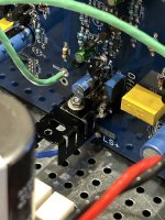
I tested in the amp with everything grounded at the XLR and RCA. Those pics are after yanking the boards to check components.

Is the offset stable when you move your multimeter leads around with the jumper in?Q1 (BD139) was bad. I checked it earlier and it seemed fine but apparently not. Luckily, ZM included 4 in the kit so I had a spare. 🙂 Currently listening to it biased at about 185mV with <5mV offset.
Not sure what you mean by moving the leads around, but the offset is stable. It was moving up and down about 3mV with the jumper in.
Wow, she's cooked. On the next one (if you haven't already) raise the resistor so it doesn't burn a trace or pad.
Question, I've stared at and compared schematics and need clarification.
I am building mosfet output version. I see R29, 30, 39 and 40 as 470R. I do not see them excluded for the MOS out stage in the notes on the SET version schematic.
They also are not listed in the contents list that came with package. I'm sure I'm missing something here,
but I'm not finding explanation in thread.
Also confused me, R53. There is a R53 location on the board. It is shown as 18k on the SET schematic, but shown as one of the 3 watt MOX resistors on the MOSFET version. With the MOSFET version, what goes in the R53 place?
BTW, tracking worked all the way to delivery!
Russellc
Oh, and what's the note on board "take care" by R45? I see it is in the 'do not mount list' for MOSFET O.S.?
Russellc
Russellc
post #624 - you have separate schmtcs for all 3 options - full mos, SET, SITQuestion, I've stared at and compared schematics and need clarification.
I am building mosfet output version. I see R29, 30, 39 and 40 as 470R. I do not see them excluded for the MOS out stage in the notes on the SET version schematic.
They also are not listed in the contents list that came with package. I'm sure I'm missing something here,
but I'm not finding explanation in thread.
Also confused me, R53. There is a R53 location on the board. It is shown as 18k on the SET schematic, but shown as one of the 3 watt MOX resistors on the MOSFET version. With the MOSFET version, what goes in the R53 place?
BTW, tracking worked all the way to delivery!
Russellc
R29,30,39,40 are smd resistors, already on pcb, part of current mirror biasing network
R53 is part of Schade circuit, populated only if you're building Schade/SET option; it is "just" ommited from schematic for full mos option, same as several other parts
Oh, and what's the note on board "take care" by R45? I see it is in the 'do not mount list' for MOSFET O.S.?
Russellc
it must be populated for full mos option, as per adequate schm
not populated for SET or SIT options, as per adequate schmts
I didnt consider the resistors were the wee little ones, explains all. And thanks for correction on my thinking regarding R45. Otherwise I would have already stepped in it. Whew. I will install now.
Thanks again...
Russellc
Thanks again...
Russellc
only logic is - part partially damaged with initial error in assembly, gave up later
Agreed. It appears Q1 went, taking Q2, R24, R21, R22, T7 and the LED. Unfortunately, I don't have replacements for the semis or led so I will need to order new parts.
I have all the "resistive" components almost finished. Caught myself mixing up a 100 R with a 100K resistor. I will post board pics as soon as done, more eyes the better. Problems are much better caught before fire up!
Hakko 951 is working excellent, good replacement for the old 929. "Sleep" mode is a little irritating, beeping all the time. Usually leave this off.
Russellc
Hakko 951 is working excellent, good replacement for the old 929. "Sleep" mode is a little irritating, beeping all the time. Usually leave this off.
Russellc
Zenmod, or anyone, are there any pics or descriptive info on the HA boards? Appears larger ones are for power supply? I was going to use teabags power supply board, got the optional HA boards as I always get all parts available! Surprise, maybe a PS board?
Thanks in advance. Will post board pics tonight after double checking my work.
Russellc
Thanks in advance. Will post board pics tonight after double checking my work.
Russellc
- Home
- Amplifiers
- Pass Labs
- Babelfish XA252 / Babelfish XA252 SIT / Babelfish XA252 SET