I tried twice to upload a video clip of Rush “Subdivisions” playing through my crappy bench test speakers. No luck.
Look on instagram @thatcherdiyaudio for the clip.
I should point out that the needles barely move on my Tannoys. Visual proof that it's the First Watt that matters most!
Come on Mr. Randy... how does it sound playing Euro Techno on the 901s?
You know... the meters give it away. 😉
Nice packaging... Real nice... and you kept the front... BLUE.
Last edited:
Still waiting to see how it handles the Hoff.... 
Seriously gorgeous build.
Seriously gorgeous build.

The secret is out! I sold my Tannoys for 901's! 🤣
In case there is any doubt at all - this amp passed my all important final test.

In case there is any doubt at all - this amp passed my all important final test.
The Toshiba mosfets that Pass tends to use in his amps (I believe he uses them in the XA25) have a slightly darker more serious sound (my impression) than a lot of other mosfets that I have heard. I like it. Does that sound like what you are hearing?If anything, the XA252 is slightly 'brighter' c.f. the commercial version and similarly very neutral and accurate. I suspect, once some dust settles, the XA252 will get the majority share of listening.
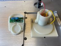
How does the blackness of the background compare? You have a very fun seat in your house. I am jealous! Also, how did you get the gauge to work?
I agree that these chinese amplifier cases are quite nice.
To be truly honest.... I'm all for the SA252 SIT.
I thought about the SET version, BUT in this particular case, given how reasonably priced the SA25 is, I think I will get the commercial version to support Nelson Pass. I mean, the guy does do something unheard of in the High End industry, so we should help him out. Even though it's quite likely that the 252SET would likely sound better -to my ears- than the SA25.
(Note: ZM too is doing something awesome... thanks and kudos ZM!)
Sure, I'll likely get it used, but that still supports Nelson. There is no way I can put the money down for a pair of XA60.8 or XA100.8 amps.
(Note: I love Randy's build, BTW. It's a stroke of genius with the Bose meters... all it needs now is the Hoff Certificate of Qualitat on the front panel ).
The SissySIT...he, he... well, couldn't pass (pun) up an amp with that name:
My SissySIT amp has real cojones!
Seriously though... does ZM realize what he's doing to us? Plethora.... plethora of what???? SissySIT... can any of you state to your friends and family that you have a Sissy-something audio amplifier at home? I just told my family it's DIY SIT-3. You'd think ZM was getting his names from a Monty Python Hungarian phrasebook? 😉 😉
OK, they sound very good... OK, OK...
And no... I will not buy those Chinese chassis. They are IP knock offs... sorry. I'm surprised customs lets them through. I'd rather pay Gianluca for his wares!
Last edited:
Also, how did you get the gauge to work?
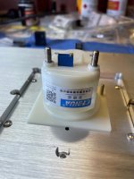
Gauge comes as VAC for mains use - see meter1 & 2
Raw gauge = 160R / 160mV full deflection -> 80mV for "half-way marker"
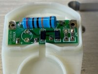
The standard diyAudio power supply boards have spare R slots across the CRC filter, which will have a dV proportional to total current draw.
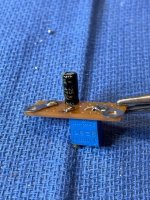
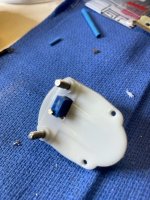
Placed trimpot (1K) in series with meter on back-side of board, then drilled hole in meter back-plate for easy access. Small electrolytic cap across meter.
Set bias for both channels, then adjust trimpot -> mid-point of meter. So registers overall bias current draw.
Attachments
The Toshiba mosfets that Pass tends to use in his amps (I believe he uses them in the XA25) have a slightly darker more serious sound (my impression) than a lot of other mosfets that I have heard. I like it. Does that sound like what you are hearing?
Yes - I suspect you might be correct!
Of interest - I have a couple of quad sets of the LSK170s from the diyAudio store lying dormant and looking for a good home ...
The mighty ZM is going to forward me some boards sans-SMD-FETs. So, it will be interesting to see what difference this makes ...
Just for the hell of it ... why not 😉
I like that. the voltage drop across the R in the CRC is a super simple way to do it. More current, larger voltage drop.
Very curious about your experiments with the LSK170s. From my limited experience with the 802D4, they are very telling speakers. You have to make them happy, or else!
Very curious about your experiments with the LSK170s. From my limited experience with the 802D4, they are very telling speakers. You have to make them happy, or else!
Just be careful, depending upon how much 'C' you have in the CRC!
I have 33000uF x2 pre/post R. So the current inrush on turn-on, and hence the dV across R, is initially quite high.
On turn-on, needle goes to "full" deflection then settles - not mechanically a threat, but if I was doing it again I would use a lower V / higher C electrolytic across the meter - say 470uF/6.3V. I just grabbed something in a tray lying spare at the time ...
Would Zen approve if I worked on an all SMT variant and post progress as well as get feedback such that it becomes as good as it can be ?
is there any better way to make amp for yourself most possibly personal?

though, don't forget that pucks are so apart with reason ......... so any parts miniaturization will not exactly save pcb area significantly
I mean - go for smd from any other reason, except making pcb substantially smaller
though, don't forget that pucks are so apart with reason ......... so any parts miniaturization will not exactly save pcb area significantly
I mean - go for smd from any other reason, except making pcb substantially smaller
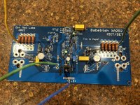
Probably not 😉 but I don't own the rights to the schematics, so not doing any changes to its design without the designers consent. And fyi, an SMT proposal is not because I think your PCB design is insufficient, it is simply an effort to improve and suppress S/N even further. I support myself on valid measurements that show a clear improvement in lower noise floor of surface mount devices due to the smaller package size. an S/N of -125 to -130dB for SMT resistors is very common and the whole circuit would benefit from this since the weakest point of a populated board is its weakest component.
these parts aren't critical at all
just take care of them being at least 100V Vce
no need for matching
just take care of them being at least 100V Vce
no need for matching
I'm down to two 100V BJT sets, both are from Toshiba and both are damned nice parts. set #1 is the 2SC2881 / 2SA1201 (SC-62 package) and set #2 is the TTC004B / TTA004B (TO-126N package). Set #2 are in my book the ideal choice with a Cob of 12 and 17pF respectively as well as 1.5A and 1.5W dissipation. They can also be mounted on the main heatsink and thus, unload the PCB from some heat generation. Even though they are TH components, the legs can be mounted on the PCB if allowed for edge mounting, aka, SMT style 😉
you previously asked about current mirror transistors, so I'm thinking solely of those
......in biasing circuit, dissipation is minimal and what you need to think regarding dissipation is just their temperature
so, same as I did - keep them on pcb, so you'll get them reasonably cold/warm (pretty much on ambient T.) and you'll get them all on same temperature ........ which is important
Within a similar temperature window is something that I tend to forget, but it is important as you say. And with that I press on
- Home
- Amplifiers
- Pass Labs
- Babelfish XA252 / Babelfish XA252 SIT / Babelfish XA252 SET