
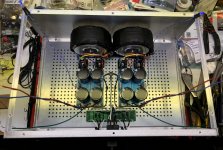
I finally got around to making one of my new power supplies operational.
My intention is to build two stereo amps to play with active multi-way speaker experiments.
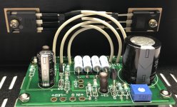
I lost patience due to limited time and discipline…and started populating my first set of Babelfish 2J boards to try with this supply.
Just wanted to vocalize some thoughts after having re-read this entire thread and taken notes.
I got my boards as a gift from Mighty ZM himself through the raffle at BAF2019…good times!
Afterwards, I ordered the full parts kit from Mighty ZM…so glad I did…kudos to him for all the hard work he does for us Lazy Greedy Boys!
ZM has already mounted the 2sk2145 critters at J101,2,3,4 and a couple other SMD bugs.
All posts I have read relating to the population of the LTP section (even as ZM stuffed it) I found point towards the same answer regarding R110 and R114…leave them empty.
So that is what I’m doing…unless I’m told otherwise.
I’m not sure how things will go given this is only the second amp I’m building outside of the documented DIYAudio kit realm. The F2J I built seemed much simpler.
Anyway, my goal is to try to maintain some flexibility for the purpose of minimizing expensive mistakes and trying different scenarios.
My intention is to build an amp with Semisouth in the lower position and the IRFP150 in the upper.
I’ve seen the various transistor combinations and source resistor values ZM has played with, and although I have hoarded enough Semisouth to try them in the upper position as well I’m not sure I will feel compelled to.
Regardless, my feeling is that I should first build the amp with IRFP150 in the upper and lower positions so that if any poop hits the fan because of a mistake I made it won’t expose the expensive Semisouth to that initial risk.
The thing is, I want to be able to change things over to the Semisouth down version as easily as possible once I confirm the initial version is functioning properly.
I’ve mounted some transistors remotely before in some ACA amps I built so that I could swap in various transistors like matched Harris IRFP as well as Semisouth.
I made my own “transistor plugs” from some DIP sockets and 16 gauge wire I had on hand that I cut up for this purpose. It worked out quite well, and the amps still function perfectly.
Since I don’t enjoy desoldering and exposing transistors (especially Semisouth) to multiple heat cycles, I think I may go this route again. Although this time I have invested in some good quality Delphi harness connectors for the cables that will attach the circuit to the transistors.
https://www.amazon.com/gp/product/B07DZ31MXL/ref=ppx_yo_dt_b_asin_title_o03_s00?ie=UTF8&psc=1
Since I know I will have at least two versions of this amp, and I may want/need to change the source resistors at some point as well, I am thinking I should mount some sockets I have on hand for these resistors (R132, 133 & R232, 233)…assuming they will accept the wire of the 3 watt resistors.
I am wondering if there is any place else in the circuit I should consider mounting sockets?
There was mention of adding 100K at R139/239 in order to make DC offset behavior more “friendly” with the Semisouth in the lower position.
There was also a few people that ran out of adjustment on their pots for Iq and DC offset adjustment that required increasing the resistors in series (R123/233 and R118/218).
Does it make sense to mount put sockets in any of these or other locations?
My intention is to build two stereo amps to play with active multi-way speaker experiments.
I lost patience due to limited time and discipline…and started populating my first set of Babelfish 2J boards to try with this supply.
Just wanted to vocalize some thoughts after having re-read this entire thread and taken notes.
I got my boards as a gift from Mighty ZM himself through the raffle at BAF2019…good times!
Afterwards, I ordered the full parts kit from Mighty ZM…so glad I did…kudos to him for all the hard work he does for us Lazy Greedy Boys!
ZM has already mounted the 2sk2145 critters at J101,2,3,4 and a couple other SMD bugs.
All posts I have read relating to the population of the LTP section (even as ZM stuffed it) I found point towards the same answer regarding R110 and R114…leave them empty.
So that is what I’m doing…unless I’m told otherwise.
I’m not sure how things will go given this is only the second amp I’m building outside of the documented DIYAudio kit realm. The F2J I built seemed much simpler.
Anyway, my goal is to try to maintain some flexibility for the purpose of minimizing expensive mistakes and trying different scenarios.
My intention is to build an amp with Semisouth in the lower position and the IRFP150 in the upper.
I’ve seen the various transistor combinations and source resistor values ZM has played with, and although I have hoarded enough Semisouth to try them in the upper position as well I’m not sure I will feel compelled to.
Regardless, my feeling is that I should first build the amp with IRFP150 in the upper and lower positions so that if any poop hits the fan because of a mistake I made it won’t expose the expensive Semisouth to that initial risk.
The thing is, I want to be able to change things over to the Semisouth down version as easily as possible once I confirm the initial version is functioning properly.
I’ve mounted some transistors remotely before in some ACA amps I built so that I could swap in various transistors like matched Harris IRFP as well as Semisouth.
I made my own “transistor plugs” from some DIP sockets and 16 gauge wire I had on hand that I cut up for this purpose. It worked out quite well, and the amps still function perfectly.
Since I don’t enjoy desoldering and exposing transistors (especially Semisouth) to multiple heat cycles, I think I may go this route again. Although this time I have invested in some good quality Delphi harness connectors for the cables that will attach the circuit to the transistors.
https://www.amazon.com/gp/product/B07DZ31MXL/ref=ppx_yo_dt_b_asin_title_o03_s00?ie=UTF8&psc=1
Since I know I will have at least two versions of this amp, and I may want/need to change the source resistors at some point as well, I am thinking I should mount some sockets I have on hand for these resistors (R132, 133 & R232, 233)…assuming they will accept the wire of the 3 watt resistors.
I am wondering if there is any place else in the circuit I should consider mounting sockets?
There was mention of adding 100K at R139/239 in order to make DC offset behavior more “friendly” with the Semisouth in the lower position.
There was also a few people that ran out of adjustment on their pots for Iq and DC offset adjustment that required increasing the resistors in series (R123/233 and R118/218).
Does it make sense to mount put sockets in any of these or other locations?
Attachments

good thinking
wherever you think you will need altering of resistor values, just solder 1pin sockets in place and push resistors in them; take care of proper contact (feel that they're grabbed in sockets)
once when you're sure of functional value of resistor, do not even bother pulling sockets out - just solder resistors in sockets
for small MF - you can push those 1pin from IC sockets, if you have those handy
same applies for small MF and for 3W Biguns, if you are able to find adequate sockets for fatter pins
regarding output parts care - thermal cycling - no need to worry about soldering as is needed to take care of not bending pins without being sure they'll end in that form for good
see in various pics of my (first, smaller) T-Bed - in most cases I bolted mosfets in place without bending pins at all, then connected them to pcb with short pieces of solid core wire - thickness of, say, 3W MOX pins , or 3A diode pins; works as charm, mosfet pins are not bent and everything good
you can do the same with any semithick wire, stranded or solid core
and yes - pcbs which will ( hope, Pony Express was better than US Post today) soon arrive to you are of much better quality than pcbs of that era

just recall that Mark (Variac) got same pcbs....... and he's having Plethora of Semisouths too .......
can't remember what he said at last BAF (chat) - it's possible that he's having SJDP too ......... depletion ones .......... those I never had and someone better/more clever than Mighty Moi could say that nothing new under the Sun can't happen ...... but me being me ..... it'll be interesting to try them in DEF arrangement ..............
🙂
wherever you think you will need altering of resistor values, just solder 1pin sockets in place and push resistors in them; take care of proper contact (feel that they're grabbed in sockets)
once when you're sure of functional value of resistor, do not even bother pulling sockets out - just solder resistors in sockets
for small MF - you can push those 1pin from IC sockets, if you have those handy
same applies for small MF and for 3W Biguns, if you are able to find adequate sockets for fatter pins
regarding output parts care - thermal cycling - no need to worry about soldering as is needed to take care of not bending pins without being sure they'll end in that form for good
see in various pics of my (first, smaller) T-Bed - in most cases I bolted mosfets in place without bending pins at all, then connected them to pcb with short pieces of solid core wire - thickness of, say, 3W MOX pins , or 3A diode pins; works as charm, mosfet pins are not bent and everything good
you can do the same with any semithick wire, stranded or solid core
and yes - pcbs which will ( hope, Pony Express was better than US Post today) soon arrive to you are of much better quality than pcbs of that era
just recall that Mark (Variac) got same pcbs....... and he's having Plethora of Semisouths too .......
can't remember what he said at last BAF (chat) - it's possible that he's having SJDP too ......... depletion ones .......... those I never had and someone better/more clever than Mighty Moi could say that nothing new under the Sun can't happen ...... but me being me ..... it'll be interesting to try them in DEF arrangement ..............
🙂


“good thinking”…
Yes…If I hadn’t turned into a sleeping robot while plugging little resistors into the boards!..or maybe it was too much solder fumes.
I forgot to mount any sockets...I only have them for small resistors anyway.
While kicking myself repeatedly, I printed and reviewed the different variations of the circuit diagram for populating with irfp150, Semisouth down and Semisouth down with the altered/reversed MOX (source resistor values).
I noticed that in both versions with Semisouth down R118 and R122 are reduced 270R and 82R respectively.
I currently have R118@820R and R122@270R.
There was mention of increasing values at R118 and R123 if one ran out of adjustment for Dc offset and Iq…I’ve no idea if I’ll run into an issue with either.
I’m just wondering if the use of the Semisouth down in the circuit automatically dictates that R118 and R122 need to be set at these lower values?
As I said…I’m not a fan of desoldering.
I’m trying to figure out if I should go back in now and pull what I mounted at R118,122 and 123 to mount sockets…or should I try and mount parallel resistors or change them altogether later when I introduce the Semisouth?
considering that those are dimensioned according to Ugs of parts used, to remind you that IRFP are in range of 4V to conduct, while SSouths are in range od 1V2 (roughly)
if you leave said resistors in value for IRFP, you will do squat of setting with SSouths in place
and the other way
if you leave said resistors in value for IRFP, you will do squat of setting with SSouths in place
and the other way

I figured that was the case.
I pulled my desoldering iron out earlier.
There’s good news and bad.
I managed to remove all the resistors at the points in the circuit I mentioned.
I also managed to mount sockets in all those locations.
There is some funkiness due to some board masking flaking away around the pads, but at least I didn’t lift any in the process.
Only problem is some of the resistors were damaged during removal.
I don’t think I have all the values on hand to replace them.
Since I’m not “Wile-Coyote-Super-Genius” circuit design guru…I usually order stuff based on BOM other genius provides…then round out order to make discounts on reasonable quantity.
No giant endless bins of resistors…though, I do have more than I expected.
I still have extra 270R for R118/122 you were so nice to send that I can switch back and forth in newly mounted sockets until things are final.
Also found some big honkin Dale 1/4 watt 221 Ohm I ordered extra of…will have to squeeze them in for R123 to start.
Already used some of the 100R Dales I was a few short on in the kit.
820R is tough one. Only thing I found was big cheap bundle of Radio Shack 1/4 watt Carbon Film resistors in my drawers with that value.
I suppose its good enough to test the circuit with the irfp so as to keep Semisouth safe.
Not sure if any of these resistors can affect the sound/performance of the circuit. I’m not into “designer” resistors.
I can change it later if I really like irfp version.
MF are simply more convenient from plenty of reasons, but I'm not avoiding carbons for testing
so go for it
so go for it
Hi ZM
I’m almost done stuffing my boards.
I left the caps for last.
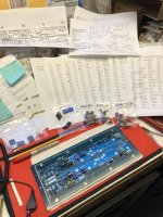
Looking at the BOM you generated from Gerbers and provided at some point earlier in thread…and comparing to circuit diagram(s) you’ve also posted.
Few questions:
BOM lists a C1 and C2 10P SMD?
Am I blind?…or do these not exist?
I only discovered (3) SMD caps on boards already mounted by Mighty U.
After referencing the circuit diagram and boards I determined them to be C103,104&105 (C203,204&205).
Did I miss something?
Second question:
C101 and C108 call for 33uF/50V
In the cap bag from kit I have (6) 10uF/63V, (2) 470uF/25V and (2) 1uF/5/100
(2) 10uF/63V work for C102(202)…
470uF/25V=C106(206)
1uF/5/100=C107(207)
Are the other (4) 10uF/63V meant to substitute for C101,108(201,208)?
If not, I have a few Elna Silmic on hand I might be able to use…although they have a bigger footprint…I might have to insulate leads and hang them off the back of the boards.
I have:
22uF/35V
33uF/35V
22uF/50V
I’m almost done stuffing my boards.
I left the caps for last.
Looking at the BOM you generated from Gerbers and provided at some point earlier in thread…and comparing to circuit diagram(s) you’ve also posted.
Few questions:
BOM lists a C1 and C2 10P SMD?
Am I blind?…or do these not exist?
I only discovered (3) SMD caps on boards already mounted by Mighty U.
After referencing the circuit diagram and boards I determined them to be C103,104&105 (C203,204&205).
Did I miss something?
Second question:
C101 and C108 call for 33uF/50V
In the cap bag from kit I have (6) 10uF/63V, (2) 470uF/25V and (2) 1uF/5/100
(2) 10uF/63V work for C102(202)…
470uF/25V=C106(206)
1uF/5/100=C107(207)
Are the other (4) 10uF/63V meant to substitute for C101,108(201,208)?
If not, I have a few Elna Silmic on hand I might be able to use…although they have a bigger footprint…I might have to insulate leads and hang them off the back of the boards.
I have:
22uF/35V
33uF/35V
22uF/50V
Attachments
ignore BOM designation (if there is "C1" and "C2")
another reason why I despise/avoid using BOMs made by anyone else - I'm having my head and my own tendency of making mistakes, so I'm usually just confused with someone else's head and tendencies
now, in schematic at first page, there are caps marked C104 and C204 - those are 10p caps, so called lag caps , or compensation caps in feedback loop
they're both near GND pads field, on top of pcb
now - C101, C102, C108 - all are the same - 10uF/63 I did change that due unification reasons, none of them being critical in value; in fact - startup/turn off behavior is more benign when C101 is decreased to 10uF
C106 - that one must be 470/16 (even if 6V3 is practically enough) and of course that 25V is good
1uF MKC Philips is bypass for that one
Hello to all again... I thought I had decided on Babelfish J, but now this seems too spicy to resist. I'll stop looking at new amp builds... Going to wait for the new monoblock chassis from Modushop to start, but planning on SS down hybrid. Shameless ask if any of you have some that you want to part with.
Going to try to get a little more juice out of it, speakers planned are 90db efficient. I know Zen Mod says to go after efficient speakers, but I'm just not that far down the rabbit hole quite yet. I feel like I've read this forum for 4 hours a day, 2 weeks, and am starting to scratch the surface. Thanks to everyone who contributes or just posts a problem. I learn a lot from all of you.
Going to try to get a little more juice out of it, speakers planned are 90db efficient. I know Zen Mod says to go after efficient speakers, but I'm just not that far down the rabbit hole quite yet. I feel like I've read this forum for 4 hours a day, 2 weeks, and am starting to scratch the surface. Thanks to everyone who contributes or just posts a problem. I learn a lot from all of you.
I'm always pointing on need for differentiation between "efficient" and "sensitive" speakers
Not repeating physical reasons behind logic, lets just take example - compare Altec VoT 15(16)" driver and similar modern, JBL or whatever 15" driver
let's say that you stumbled on perfect pair for comparison, both having same db/W/m figure
now, Altec is - what - 50W or so, while modern one is (minimum) 350W
take your weeny 20W amp ( which was damn good figure in Yore) and try it with GranPa and then with Youngster
guess how much layers you can hear with GranPa in covered range, and what mush of layers you can hear with Youngster
so, if you say - my spks are 90db/W/m ........ that's just tiny part of thse story
my RCA LC1B are sorta 91.5db/W/m but I can use them as microphone, how sensitive they are
and all of my amps are having just half of declared power, because they're 16R
so, preaching done, which exact speakers you have?
Right now I have a pair of Polk Tsi400, but I thought I was going to get a good deal on Sonus Faber Venere 3.0. I'm not really committed unless I get a good deal. I've been down the headphone tube amp rabbit hole for quite some time, and now am just getting around to 2 channel. Money doesn't grow on trees for me 🙂I'm always pointing on need for differentiation between "efficient" and "sensitive" speakers
Not repeating physical reasons behind logic, lets just take example - compare Altec VoT 15(16)" driver and similar modern, JBL or whatever 15" driver
let's say that you stumbled on perfect pair for comparison, both having same db/W/m figure
now, Altec is - what - 50W or so, while modern one is (minimum) 350W
take your weeny 20W amp ( which was damn good figure in Yore) and try it with GranPa and then with Youngster
guess how much layers you can hear with GranPa in covered range, and what mush of layers you can hear with Youngster
so, if you say - my spks are 90db/W/m ........ that's just tiny part of thse story
my RCA LC1B are sorta 91.5db/W/m but I can use them as microphone, how sensitive they are
and all of my amps are having just half of declared power, because they're 16R
so, preaching done, which exact speakers you have?
edit: Also have a pair of Halford Margaritas, a local guy to me. They get tonality and clarity so right.
via ggle- neither Polks, especially not Sonus, are making me feel any warmth
Margaritas, even if small, are closer to my sense of necessary speaker sensitivity
so, think lower powered (for today's standards) bigger cones ....... say that Zu is closest (by approach) what I can mention in this context
you didn't put info in your profile from where you are, so I can't give you more specific info, based on location
I know for some things available in States, but more of them are familiar to me on this (Eu) side of Big Pond
more sensitive speaker is allowing use of smaller amp, and smaller amp is easier and cheaper to be made properly, than big amp
btw. - why not making speakers, too?
- Home
- Amplifiers
- Pass Labs
- Babelfish ᄅſ....or FW J2 on Steroids .... or Not your Father's J2!