Let me take baby steps! I've thought about building speakers, but I just need to build the amp first. It's probably the only amp I'll ever build (I bet a lot if posters here once said that). It will take me some time.via ggle- neither Polks, especially not Sonus, are making me feel any warmth
Margaritas, even if small, are closer to my sense of necessary speaker sensitivity
so, think lower powered (for today's standards) bigger cones ....... say that Zu is closest (by approach) what I can mention in this context
you didn't put info in your profile from where you are, so I can't give you more specific info, based on location
I know for some things available in States, but more of them are familiar to me on this (Eu) side of Big Pond
more sensitive speaker is allowing use of smaller amp, and smaller amp is easier and cheaper to be made properly, than big amp
btw. - why not making speakers, too?

OK…here I am finally ready to test a first channel after starting this project in July
I’m being as cautious as possible.
Testing with irfp150 up and down to be safe.
Once I know both channels work…I’ll install Semisouth, change out required resistors, reset pots and start over.
ZM notes on start up:
“regarding first run and setting procedure ..... if you did check everything and you're happy how smart and capable you are , and you were smart enough to pre-set trimpots somewhere in mid position ( and you confirmed that with ohmmeter) .......
- you were so smart to solder PSU wires just to one channel pcb , or in case you did dual mono - put mains fuse just for channel you're working on now;
- no load connected to output
- both inputs ( pos and neg) grounded
- connect (( with miniclips) one DVM across one of 3W 1R resistors ;
- connect second DVM to output of same channel
- bang bloody thing ON
- fiddling with both Px01 and Px02 , set that you have as close to 0mV you can get on output and (say) 850mV across said 1R/3W resistor ; that corresponds to 1A7 of Iq
let am get some heat , keep one eye on both DVMs
repeat some trimpot twiddling , if necessary , up to temp equilibrium
....................... repeat same procedure with second channel “
-My trimpots are set in the middle (confirmed with DVM)
-Only one channel installed in the case…can’t fire only one PSU with how the inlet is wired, but not an issue in this case
-no load on output
-I shorted inputs with an old RCA plug I have with wires shorted and soldered (hope this is same as grounded both inputs)
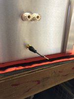
-First DVM is across 1 Ohm resistor at R236
-Second DVM at binding posts
Before I “Bang the Bloody Thing On”…anyone see anything incredibly stupid in the pictures?
Also…I think ZM wrote that bringing these amps up to slow with a variac can be problematic.
I do have a variac on hand.
Is there anything else I can do to prevent a melt down if I screwed something up on the boards before “banging it on”?
I’m being as cautious as possible.
Testing with irfp150 up and down to be safe.
Once I know both channels work…I’ll install Semisouth, change out required resistors, reset pots and start over.
ZM notes on start up:
“regarding first run and setting procedure ..... if you did check everything and you're happy how smart and capable you are , and you were smart enough to pre-set trimpots somewhere in mid position ( and you confirmed that with ohmmeter) .......
- you were so smart to solder PSU wires just to one channel pcb , or in case you did dual mono - put mains fuse just for channel you're working on now;
- no load connected to output
- both inputs ( pos and neg) grounded
- connect (( with miniclips) one DVM across one of 3W 1R resistors ;
- connect second DVM to output of same channel
- bang bloody thing ON
- fiddling with both Px01 and Px02 , set that you have as close to 0mV you can get on output and (say) 850mV across said 1R/3W resistor ; that corresponds to 1A7 of Iq
let am get some heat , keep one eye on both DVMs
repeat some trimpot twiddling , if necessary , up to temp equilibrium
....................... repeat same procedure with second channel “
-My trimpots are set in the middle (confirmed with DVM)
-Only one channel installed in the case…can’t fire only one PSU with how the inlet is wired, but not an issue in this case
-no load on output
-I shorted inputs with an old RCA plug I have with wires shorted and soldered (hope this is same as grounded both inputs)
-First DVM is across 1 Ohm resistor at R236
-Second DVM at binding posts
Before I “Bang the Bloody Thing On”…anyone see anything incredibly stupid in the pictures?
Also…I think ZM wrote that bringing these amps up to slow with a variac can be problematic.
I do have a variac on hand.
Is there anything else I can do to prevent a melt down if I screwed something up on the boards before “banging it on”?
Attachments

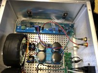
nothing to complain about , except fact that you wrote - can't fire just one channel
it is absolutely necessary that each Donut is having own mains (primary) fuse
fact that IEC and switch are common for both Donuts is irrelevant for above
it is absolutely necessary that each Donut is having own mains (primary) fuse
fact that IEC and switch are common for both Donuts is irrelevant for above
Once you change to the SS, be prepared to swap the resistor in series with the bias pot. I don’t recall where I ended up (it’s not far off) but it was necessary to bias the SS properly. Not your priority at the moment I know, but making note while I’m thinking of it.
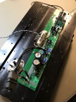
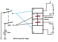
Ugh…I was trying to follow the wiring example you posted for the this side of pond using your HA!/NTC boards. (Pic below)nothing to complain about , except fact that you wrote - can't fire just one channel
it is absolutely necessary that each Donut is having own mains (primary) fuse
fact that IEC and switch are common for both Donuts is irrelevant for above
I just thought that since both legs were fused in my entry/switch module (neutral and hot) that was the only difference to the diagram.
I took a pic of how it is currently…and drew over it with the editor.
I hope you can see what I’m thinking…is this the proper way to add a fuse for each donut?
Strange thing is…both legs(neutral and hot) will still be fused in entry module…then the hot line will have a secondary fuse going to each donut’s NTC boards?
Is moving the gate resistor for the mosfets necessary due to the leads as well?
I’m OK with the series resistor for bias pot…mounted sockets there so I can change the resistor when I mount Semisouth if needed.
Attachments
if you install separate fuses for each Donut ( as it must be) , just put double or triple ( of separate ones) value for fuse situated in IEC itself
calculus is simple VA of Donut divided with V, then first closest standard value
even if lower is closest standard value, use that; in case of often popping fuses during power up, change to first higher standard value
calculus is simple VA of Donut divided with V, then first closest standard value
even if lower is closest standard value, use that; in case of often popping fuses during power up, change to first higher standard value
you'll hate me ....... for using Papa's catch
- this one I'm working on

I understand his stance ...... amps, per se, are not so important - as fun while working on them is
of material things I have , important are those I can hardly make again (or at all) - my RCA spks, then those things I got as gift
counting those (gifts) I'm not proud nor satisfied, I'm simply happy .... to know those people I got gifts from
- this one I'm working on
I understand his stance ...... amps, per se, are not so important - as fun while working on them is
of material things I have , important are those I can hardly make again (or at all) - my RCA spks, then those things I got as gift
counting those (gifts) I'm not proud nor satisfied, I'm simply happy .... to know those people I got gifts from
Last edited:
Donuts are Avel Lindberg 250va…divided by 115-120 line voltage points to a 2 Amp fuse for each donut and 4 Amp in the power inlet.
Most of the FW PS schematics I’ve seen call for Slow Blow…that is what I was going to use.
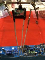
Do I need to worry about moving the gate resistors so they are at the end of the leads for the mosfets?
Most of the FW PS schematics I’ve seen call for Slow Blow…that is what I was going to use.
Do I need to worry about moving the gate resistors so they are at the end of the leads for the mosfets?
you're good for now
though, as you have space, and you need to suffer for not being present at that class, desolder those wires and put gate resistor ditto at mos pin**
gate resistor on pcb - either replace with 0R one, or solder 0R across it
**which is proper engineering practice
though, as you have space, and you need to suffer for not being present at that class, desolder those wires and put gate resistor ditto at mos pin**
gate resistor on pcb - either replace with 0R one, or solder 0R across it
**which is proper engineering practice
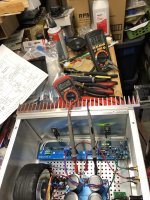
I’m working on fixing one thing at a time.
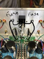
Almost done rewiring and installing separate fuses for the supplies.
I’m not positive about how to ensure that once I move the gate resistor to the end of my leads it will have some structural rigidity so the thin resistor wire doesn’t fatigue and break while I’m swapping out transistors. Maybe putting some shrink tubbing over it will be enough?
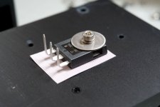
I’ve seen the use of washers and even drilled coins for clamping transistors to distribute force better on heatsinks in several builds.
When I was mounting mine, I pulled a few washers out to try. I scratched my head over the dilemma of what to do with the plastic insulating shoulder washers I’ve become accustomed to using to clamp transistors.
The shoulder is not deep enough to pass through a washer and still engage and center the transistors.
Placing the shoulder washer under a big washer is pointless because then the washer doesn’t make contact with the top of the transistors properly.
It only just occurred to me that perhaps the shoulder washers are completely unnecessary with these transistors.
I tested for continuity with my DVM between the metal back of the transistors and the mounting hole as well as face and there is obviously no continuity.
I’m assuming that the mentality is as long as a mounting pad of some sort is used to isolate the transistors from the heatsinks that it doesn’t matter if the mounting hardware is isolated with these transistors?
Almost done rewiring and installing separate fuses for the supplies.
I’m not positive about how to ensure that once I move the gate resistor to the end of my leads it will have some structural rigidity so the thin resistor wire doesn’t fatigue and break while I’m swapping out transistors. Maybe putting some shrink tubbing over it will be enough?
I’ve seen the use of washers and even drilled coins for clamping transistors to distribute force better on heatsinks in several builds.
When I was mounting mine, I pulled a few washers out to try. I scratched my head over the dilemma of what to do with the plastic insulating shoulder washers I’ve become accustomed to using to clamp transistors.
The shoulder is not deep enough to pass through a washer and still engage and center the transistors.
Placing the shoulder washer under a big washer is pointless because then the washer doesn’t make contact with the top of the transistors properly.
It only just occurred to me that perhaps the shoulder washers are completely unnecessary with these transistors.
I tested for continuity with my DVM between the metal back of the transistors and the mounting hole as well as face and there is obviously no continuity.
I’m assuming that the mentality is as long as a mounting pad of some sort is used to isolate the transistors from the heatsinks that it doesn’t matter if the mounting hardware is isolated with these transistors?
Ya no shoulder washers with these big power parts. You want a big washer or coin with a hole, split washer (lock), Keratherm or mica / grease isolator. Torqued to 8 in. lbs. (6-32 or M3 screw) if we're going for truly proper construction. Gate wire can be small gauge, no real current and low voltage. A small wire won't put much strain on a resistor hanging off a MOSFET pin.
Fired my first channel just now after finally finishing suggested revisions.
PS is now wired with separate fuses for each donut…so now I can power one channel at a time.
I also removed the gate resistors from the boards (insert cursing here) and installed new gate resistors at the other end of the leads near the transistors.
Lastly…added some moderately bigger fender washers to help dissipate force clamping transistors to the heatsinks.
So nothing let out any magic smoke yet.
I haven’t even touched Iq or DC offset pots
After about 10 minutes I’ve got 690mV across R236 and the DC offset is reading 0.00 mV on my cheap old DMV.
When I first fired it up Iq was slightly higher than 700mV and offset was maybe .05 mV.
My notes say the goal is to fiddle the Iq up to 850mV and try to zero the offset.
I just wanted to check if I should be aiming for a lower Iq at first because these Heatsink USA sinks I built this case with are roughly equivalent to a 4U/300 case (7” x 12” x 1 5/16”)?
If so, I’m not familiar with the math.
If I’m setting for a lower Iq how do I figure out the mV figure I want across R236?
Attachments

leave it as is regarding settings, remove mains fuse for that channel so you can easy proceed with second channel
when you get to thermal equilibrium (having both channels operating and heating the case), we'll see by temperature where you need to go with Iq
when you get to thermal equilibrium (having both channels operating and heating the case), we'll see by temperature where you need to go with Iq
I got to fire second channel this AM…nothing blew up.
Almost same behavior as first channel.
Iq virtually identical at start up and behavior after warming up.
Offset is not as pretty…start up at about 200mV and settling down to about 120mV
I fiddled with offset pot to make sure it responds…seems to work…but am letting things heat up more.
I know the real goal at this point is to get it to heat equilibrium…even with just cover placed on top…and take temperature measurements.
Should I take temps at transistors?…or a certain part of heatsink?
My intention was to install Semisouth down…which will require swapping them in along with changing values at R118 and R122 at least. Adjustment again to follow.
I’d like to listen to the amp with IRFP as well as Semisouth down.
I was thinking of setting up one channel each way to compare.
I’m thinking I need more DVM besides the two I have if I want to try this and monitor/adjust properly with both channels set up differently while they respond to equilibrium?
P.S. During power down DC offset climbs at output to about 3.5 V and then very slowly drops after amp has already been shut down over several minutes. Is this a problem?
Attachments

no problems with DC offset as you explained - normal behavior for amp and with load (speaker) all you could hear is slight and warm Pop!
temperature at mid top of heatsink, by Paparule (enclosed)
take care of temp difference of room now vs. Summer ( your habits of heating/AC)
my advice for full mos vs. SS down is - leave it as is now ) full mos) and use it and listen for a month or so
that way amp will sit in your ears (perception)
then change to SS and give it a month
amount and nature of pleasure - one vs. another will tell you all you need
as Mr. Linkwitz use to say - I prefer long listening tests to blind ones

edit: as checking measure - but only if you have contact type temp. meter - carefully measure temp of mosfets at mid pin, at ceramic case and on heatsink ditto to mosfet case
write here
if you don't have that type of meter, just chill and trust in your proper procedure for establishing thermal interface
temperature at mid top of heatsink, by Paparule (enclosed)
take care of temp difference of room now vs. Summer ( your habits of heating/AC)
my advice for full mos vs. SS down is - leave it as is now ) full mos) and use it and listen for a month or so
that way amp will sit in your ears (perception)
then change to SS and give it a month
amount and nature of pleasure - one vs. another will tell you all you need
as Mr. Linkwitz use to say - I prefer long listening tests to blind ones
edit: as checking measure - but only if you have contact type temp. meter - carefully measure temp of mosfets at mid pin, at ceramic case and on heatsink ditto to mosfet case
write here
if you don't have that type of meter, just chill and trust in your proper procedure for establishing thermal interface
- Home
- Amplifiers
- Pass Labs
- Babelfish ᄅſ....or FW J2 on Steroids .... or Not your Father's J2!