try dealing with one channel at a time
leave second unpowered
can't see from that picture - do you have NTCs connecting audio GND and chassis?
small ones , 10-15R, around 10mm Dia, place for them at output side of Cap Bank pcbs
leave second unpowered
can't see from that picture - do you have NTCs connecting audio GND and chassis?
small ones , 10-15R, around 10mm Dia, place for them at output side of Cap Bank pcbs
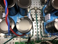
The leads of NTCs I had on hand wouldn’t fit in the holes on the Cap Bank PCB. They are 13mm 10 Ohm 6A.
I had to put a jumper in the board where the NTC mounts and then put the NTCs inline between the PCB chassis cable pad and chassis ground point.
I had to put a jumper in the board where the NTC mounts and then put the NTCs inline between the PCB chassis cable pad and chassis ground point.
try dealing with one channel at a time
leave second unpowered
can't see from that picture - do you have NTCs connecting audio GND and chassis?
small ones , 10-15R, around 10mm Dia, place for them at output side of Cap Bank pcbs
Attachments
OK, that's good
what's happening if you have just one channel powered, input grounded - is there any buzz in (test) speaker?
btw - I see you're using RCA for input; did you grounded Neg input on pcb (that being necessary if you're going for SE input)?
what's happening if you have just one channel powered, input grounded - is there any buzz in (test) speaker?
btw - I see you're using RCA for input; did you grounded Neg input on pcb (that being necessary if you're going for SE input)?
I think that may be the problem.OK, that's good
what's happening if you have just one channel powered, input grounded - is there any buzz in (test) speaker?
btw - I see you're using RCA for input; did you grounded Neg input on pcb (that being necessary if you're going for SE input)?
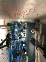
I had noticed the “INGND” labeling on the PCB near the input pads…but didn’t know what to make of it since I hadn’t come across anything in the notes or thread about it…it slipped my mind to ask.
Do I just need a jumper from the “INGND” pad to the (-) negative terminal pad where I mounted the euro block?
Attachments

well, schematic on page 1 is clearly showing Positive input and Negative input and INGND
that, amp being made to have Balanced ( XLR) input
when you want to use SE (RCA) input, your signal Hot goes to Positive Input, Signal GND goes to INGND, and Negative input must be shorted to GND ( InGnd)
that, amp being made to have Balanced ( XLR) input
when you want to use SE (RCA) input, your signal Hot goes to Positive Input, Signal GND goes to INGND, and Negative input must be shorted to GND ( InGnd)
Sorry…just a clueless oversight on my part…my schematic reading skills are minimal and circuit design is beyond me…no way for me to recognize the balanced input to be honest (though it’s obvious now that you pointed it out!).
I want to make sure I understand your instructions properly.
I should pull the euro block off the board at the input pads so that I can connect my RCA plug hot wire to the input (+) positive pad and the ground ring wire on my RCA plug should be connected to the “INGND” pad?
Then place a jumper between the in (-) negative pad and “INGND” pad?
Can I accomplish the same thing by just putting a jumper between the “INGND” pad and the (-) negative pad and leave the euro block and wiring as is?
Attachments
Last edited:
you can leave euro block (argh!!! piece of drek)
just make short/bridge between GND and IN-
same as you need to do when you're making Aleph J
RCA Hot goes to IN+
RCA GND goes to INGND
IN- shorted to INGND
just make short/bridge between GND and IN-
same as you need to do when you're making Aleph J
RCA Hot goes to IN+
RCA GND goes to INGND
IN- shorted to INGND
Thanks ZM…sorry for the hand holding…and the euro blocks!
I was thinking how much you dislike them and spade connectors as I was mounting them for my signal and power connections…but I felt it was necessary for someone with my experience level.
I’ve already had the boards in and out of the case 2 or 3 times.
More than likely, I would have lifted a pad or damaged something if I had to desolder/solder each time.
I only have desoldering braid and what looks like Fred Flinstone’s desoldering iron to work with.
This project has been the most ambitious for me so far.
Sometimes I feel like I’m trying to speak a foreign language with no knowledge of its grammar…just because I know some vocabulary doesn’t mean I know what’s going on.
just relax and no hurry
we are here to help, without asking for EE Degree
patience and some common sense are good enough .... for start
we are here to help, without asking for EE Degree
patience and some common sense are good enough .... for start
You've done remarkably well imo. I haven't even begun my amps, but just reading your thoughts and seeing your pictures/layout helps me. Thanks for posting! And thanks to Zen Mod for helping you!Thanks ZM…sorry for the hand holding…and the euro blocks!
I was thinking how much you dislike them and spade connectors as I was mounting them for my signal and power connections…but I felt it was necessary for someone with my experience level.
I’ve already had the boards in and out of the case 2 or 3 times.
More than likely, I would have lifted a pad or damaged something if I had to desolder/solder each time.
I only have desoldering braid and what looks like Fred Flinstone’s desoldering iron to work with.
This project has been the most ambitious for me so far.
Sometimes I feel like I’m trying to speak a foreign language with no knowledge of its grammar…just because I know some vocabulary doesn’t mean I know what’s going on.
Thanks for the words of support Porteroso.
As ZM said…Patience… it’s probably the hardest and yet most valuable skill!
I’m struggling to maintain some…I just have to take a deep breath and walk away sometimes.
So I disassembled everything again today to get the boards out and solder the jumpers between the “INGND” and (-) negative pads.
After re-assembly, I powered the amp and tested initial DC offset to see if it was about the same since I didn’t know if the change to grounding on the input would affect that.
Offset appeared about the same, but I decided to let the amp get up to temp equilibrium and recheck it.
I ended up tweaking out about 35mV of offset on each channel.
After that, I powered the amp down and pulled a fuse on one channel so I could do a sound test on each channel separately.
I used my inexpensive Aura test speakers wired up for an 8 Ohm load again.
I used my iPhone as a source with a lightning to mini stereo/RCA adapter.
It seemed to work properly…I got sound.
There was a little noise, but after fiddling with the lightning adapter cable a little it seemed to disappear…it seemed like it wasn’t seated properly in the phone port.
I repeated the test the same way on the second channel and got the same results.
After this I figured I was good to go and buttoned the case up to bring upstairs and test in one of my systems.
Unfortunately, as soon as I fired the amp up in the system it started buzzing like crazy again.
I didn’t understand why (nothing new) and proceeded to go through a trial and error with the connections to the amp to see if the sound would go away.
It didn’t matter if the inputs were connected or not…or if they were shorted.
It didn’t matter if I used the iPhone as a source or if the system with my preamp and etc. were connected.
I tried pulling the fuses and powering each channel alone with no affect except the noise was reduced because it only came from one channel.
I tried eliminating connection with the system altogether and even used a different outlet and cable to power the amp.
I then tried to recreate how I had tested the amp on the bench downstairs.
What I realized was that the test speakers produced much less noise, but that ultimately the noise was there. It was at much lower level it seems because the speakers are so small and and don’t have nearly the sensitivity of the 10” fullrange drivers I use in the system.
I pulled the amp cover and continued to try different variations of the source, speakers and etc. to reconfirm what was going on.
At one point I started to examine the power supply and signal wiring again to see if the noise would change if I shifted things in any way in the case.
I lifted the twisted power cable that runs from the cap bank to the amp boards and it made a noticeable difference in the level of the noise…but it didn’t eliminate it. Pushing the cables back down toward the top of the caps caused it to get louder again.
I can’t help but get the feeling I’ve done something wrong with the supply and case layout and its injecting noise into the circuit.
I’m not sure what to do to confirm whether the power supply is the source of the noise or not.
I’m open to suggestions as to how to proceed.
Something I’m wondering about after considering what might be wrong due to my power supply…I worry it might have been a bad idea when I thought it would improve things.
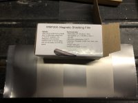
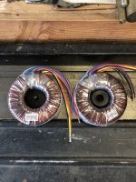
I wrapped my transformers with a shielding material to help prevent noise issues if I ever installed an amp in these cases that used signal transformers…as I think I saw ZM did in one of the SissySIT builds for a friend.
Its taped in place around the periphery of both transformers.
I’ve attached a pic of the shielding.
Could this actually be having the opposite affect by being taped directly to the outside of the transformers?
Attachments
I will revisit your pictures tonight, hoping to see something fishy
if you wrapped that material simply around Donuts, isolated and not being connected to anything ( chassis), then you did good
my Donuts Vendor is doing exactly the same - practically same material used for cores, wound in 3 or 4 layers around circumference, then everything taped with isolation
one thing - check polarity of wires coming from RCA to pcb
@chromenuts -
To be sure I've understood. At one point on your test bench / build area, you had no noise / hum. However, one of your thoughts might be that the hum was present but inaudible with your test speakers (less sensitive than full rangers). Is that correct?
Then you took the amp somewhere else, buttoned it up, and connected it to some other gear in addition to your 10" full range speakers. Then you heard hum. Is that also correct? However, you still hear the hum with inputs shorted and/or nothing connected to the inputs at all.
If so, a few other things you may consider trying in order to isolate the area of the root cause(s) are:
Bring the auras up the main area and hook them up.
- If you still can't hear the hum, then your hypothesis that it's the sensitivity of the Aura's ... fits. Continue looking for things 'within the amp'.
- chassis ground isolated (~10ohm different if those are CL-60s in your pic) from audio gnd at all points. Check RCA input gnd point and speaker outs ground point.
- check that chassis ground carries around all panels. Good continuity between all panels of the chassis.
- As ZM said, make sure inputs are wired correctly.
- If you can hear it in your main listening area with the Auras, then start looking for things about the main listening area that differ from your bench. DC on the mains? Any florescent lamps on the circuit or nearby? Modems / Routers? Anything using the same outlet that you can unplug to check? My M2x build gave me fits on the bench until someone helped me realize that using an outlet from a florescent magnifying lamp wasn't a super idea. 😀 Hummmmmmmmmmmm! I think the signal transformer was very sensitive to the radiated EMI with the top off and/or it was contaminating the AC line. Dunno. Either way, I turned the lamp off, and voila.
Could be one of many things or a few things, but narrowing to "amp circuit" or "environment" can help narrow things quite a bit.
As always, listen to the mighty ZM. My experience with my goof-ups pales in comparison to his actual expertise. 😀
Hi ZMI will revisit your pictures tonight, hoping to see something fishy
if you wrapped that material simply around Donuts, isolated and not being connected to anything ( chassis), then you did good
my Donuts Vendor is doing exactly the same - practically same material used for cores, wound in 3 or 4 layers around circumference, then everything taped with isolation
one thing - check polarity of wires coming from RCA to pcb
The shielding material wasn’t cheap…mine only goes around once. Who knows if that even did anything except create more work for me.
The shield is isolated…no connection to ground.
My RCA positive and negative connections are connected to the correct pads on the PCB.
I have thought of one other thing I did that I’m worried might have been brilliantly stupid.
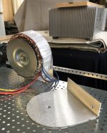
Back in August when I was making the mounts for the transformers we went through the debacle of how the brackets couldn’t be “U” shaped cradles (or they would create a short in the transformers) and I had to change them to “L” brackets.
When I finally got that straightened out and was mounting the transformers on the “L” brackets I noticed they kept sliding down wanting to make contact with the floor of the case.
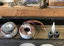
I figured I needed a bushing to help keep them centered on the mounting bolt.
My solution was some rubber equipment feet I had lying around unused.
They are made of rubber with a steel washer at the mounting point.
I had to lube them up with some silicon and use some pressure to press them into the center of the transformers. Pics attached.
I’m wondering if I could have caused some damage to the windings or if the bushing created a problem for some other reason?
The voltage I’ve tested coming from the transformers appears to be normal.
I’m wondering if they would still operate properly if I had created any kind if short.
Attachments
Hi IAIMH@chromenuts -
To be sure I've understood. At one point on your test bench / build area, you had no noise / hum. However, one of your thoughts might be that the hum was present but inaudible with your test speakers (less sensitive than full rangers). Is that correct?
Then you took the amp somewhere else, buttoned it up, and connected it to some other gear in addition to your 10" full range speakers. Then you heard hum. Is that also correct? However, you still hear the hum with inputs shorted and/or nothing connected to the inputs at all.
If so, a few other things you may consider trying in order to isolate the area of the root cause(s) are:
Bring the auras up the main area and hook them up.
- If you still can't hear the hum, then your hypothesis that it's the sensitivity of the Aura's ... fits. Continue looking for things 'within the amp'.
- chassis ground isolated (~10ohm different if those are CL-60s in your pic) from audio gnd at all points. Check RCA input gnd point and speaker outs ground point.
- check that chassis ground carries around all panels. Good continuity between all panels of the chassis.
- As ZM said, make sure inputs are wired correctly.
- If you can hear it in your main listening area with the Auras, then start looking for things about the main listening area that differ from your bench. DC on the mains? Any florescent lamps on the circuit or nearby? Modems / Routers? Anything using the same outlet that you can unplug to check? My M2x build gave me fits on the bench until someone helped me realize that using an outlet from a florescent magnifying lamp wasn't a super idea. 😀 Hummmmmmmmmmmm! I think the signal transformer was very sensitive to the radiated EMI with the top off and/or it was contaminating the AC line. Dunno. Either way, I turned the lamp off, and voila.
Could be one of many things or a few things, but narrowing to "amp circuit" or "environment" can help narrow things quite a bit.
As always, listen to the mighty ZM. My experience with my goof-ups pales in comparison to his actual expertise. 😀
The behavior with the test speakers is the same everywhere.
I’ve tested with them upstairs where the system is located, and since then re-tested on the bench again to confirm. There is always a very faint buzzing/hum.
I have to put my ear close to the speakers to hear it. It may have been more obvious upstairs because it is a quieter environment.
My bench is in the furnace room…I actually shut it down when I tested…but I think I just missed the noise the first time around.
One thing you mentioned that caught my attention:
“- chassis ground isolated (~10ohm different if those are CL-60s in your pic) from audio gnd at all points. Check RCA input gnd point and speaker outs ground point.
- check that chassis ground carries around all panels. Good continuity between all panels of the chassis.”
I get continuity throughout the case panels from the grounding point I placed in the center of the floor between my two cap bank boards.
This point is where my IEC is grounded along with the two “chassis” ground leads from the cap banks which have current limiters mounted inline.
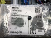
I’ve attached a pic of the CLs I’m using.
When I use my DVM to “ring out” continuity of the case panels I get a clean ring on every panel.
When I test my signal input and output grounds I would expect nothing based on you saying they should be isolated from chassis ground.
Instead I am getting a ragged sounding ring which says there is some kind of continuity happening between my chassis ground point and my signal grounds.
I don’t know why that is if you say they should be isolated.
Attachments
Regarding my concerns about the bushings I pressed into the transformers for mounting.
I looked up the manufacturer’s wiring diagram. They are dual primary and dual secondary.
From there I proceeded to ring out the windings to confirm if there were any shorts.
The secondaries are all intact and there were no shorts between them.
I found no shorts between the secondaries and primaries.
When testing the primaries themselves I found continuity between all leads where they connect o the NTC boards (no where else to test).
This appears to be due to the fact that I cannot disconnect them from the NTC boards.
I have a second set of the same NTC boards already populated and wired the same way as I used in this amp.
I tested a brand new Antek transformer with dual primaries/secondaries with these boards.
When the Antek is disconnected the primaries ring indepedantly with no shorts between. When I connect the primaries of the Antek to the NTC boards as I have done in the amp I get continuity across all leads.
I know this isn’t full proof deductive reasoning, but it seems to indicate there is no unusual behavior.
The only other concern I might have would be if the pressure exerted by the rubber bushings inside the transformers could be causing a problem with the windings proper operation.
I also disconnected my input and output grounds and confirmed again that there are no shorts to the case.
...................
I’ve attached a pic of the CLs I’m using.
When I use my DVM to “ring out” continuity of the case panels I get a clean ring on every panel.
When I test my signal input and output grounds I would expect nothing based on you saying they should be isolated from chassis ground.
Instead I am getting a ragged sounding ring which says there is some kind of continuity happening between my chassis ground point and my signal grounds.
I don’t know why that is if you say they should be isolated.
The continuity between safety (chassis) ground and audio ground is through the in-rush current limiter, which has a cold resistance of 10 Ohm. Set your meter to Resistance and measure the resistance. It should read 10 Ohm.
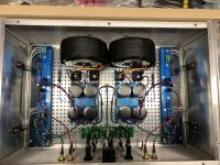
One thing that I noticed from your picture of your amplifier is that your audio inputs and outputs on your back panel are very close to the AC input and AC wiring. Combined with the loose, untwisted wires, that may contribute to hum.
Hi Ben
I tested resistance between my chassis ground and the connection points on the PCBs for (-) negative input and output (RCAs and binding posts are still disconnected).
I got 14 Ohms on one channel and 13 Ohms on the other. Seems to be acceptable.
I thought about your comment regarding the AC wiring proximity to the signal wiring.
I had originally taken the deluxe backplate of a Madisound 4U case I purchased on sale after these cases were being built and traced the layout for the back panel on these.
One would think that would be a safe move.
Of course, then I had to change things recently because ZM instructed me that seperate fuses were a must for dual mono transformers. My choices were limited to make it reasonable with existing wiring and caused things to get more crowded.
It didn’t seem logical to extend the binding post wiring just so I could twist it a few times while it ran to the PCBs when considering the locations at opposite ends of the boards for the positive and negative output connections. Maybe I need to consider otherwise.
I twisted my input wiring and tried to make it short yet manageable to handle and connect. I can probably shorten it more.
I’m starting to think that I may have to assemble some other kind of test bed/power supply to try and rule out the major question of is the problem in the supply/case layout or in the amp boards.
It's always best to keep AC wiring as far as possible from amplifier wiring and twist all wires together with their returns.
diyAudio member Bonsai has a good write-up on amplifier noise and hum that I use as a guide in my amplifier building:
https://hifisonix.com/wordpress/wp-content/uploads/2019/02/Ground-Loops.pdf
Looking at your amplifier, is the AC wiring from the back of the amplifier to the front twisted together?
As for the V+, V-, and Gnd from the power supply, following Bonsai's recommendation, I twist them together from power supply to amplifier board. If the Gnd point on the amplifier board is separated from the V+ V- location, I keep the Gnd twisted with the V+ V- wires to that point, and then take the Gnd wire to the Gnd point on the board. Likewise I would do the same with the speaker positive and negative if their connection points are not next to each other - twist the wires together from the connectors at the back panel and take both wires to the speaker positive connection point on the board, and then the speaker negative to the Gnd point.
I twist together all wires and their returns starting at the IEC connector all the way to the speaker connectors and points in between.
Some may say that my twisting of wires is obsessive and not necessary as their amplifiers with untwisted and loose wires are not noisy at all. Their speakers may not be very sensitive or their tolerance for hum my be very high. The reason I do it is that my speakers are very sensitive (103 dB) so I do as much as I can from the start. Then if there is noise after that, I have already eliminated sloppy wiring as a cause and look for other reasons.
In your case the wiring may or may not be the major cause of the hum. However if you eliminate potential causes you will then be able to get closer to finding the problem.
Another point that I would like to add: toroid transformers may "leak" at exit locations of wires. I have found with the Antek transformers that I use that the lowest noise position is with the wire exit locations pointing to the front or back of the amplifier if the toroid is mounted horizontally and the wire exit location pointing down if the toroid is mounted vertically. I see that your toroids' wire exit location is pointing a bit towards the left channel. Rotating the toroids so that the wire exit is pointing straight down may help.
Last edited:

- Home
- Amplifiers
- Pass Labs
- Babelfish ᄅſ....or FW J2 on Steroids .... or Not your Father's J2!