Hi Ben
Thanks for the feedback and link. I’m going to read through it now.
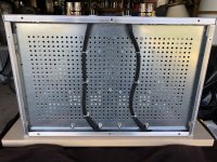
The AC wiring from the NTC board in the back of the case runs under the perforated steel base plate and is twisted the entire way (hot and nuetral twisted for each primary and also the two pairs twisted and protected inside loom)…a pic is attached.
I wasn’t sure what to try next and decided the easiest thing was to remove the bushings from the center of the transformers just to put my mind at rest that they weren’t causing any issues.
It didn’t seem to make a difference when I fired up one channel and gave it a listen on the bench.
I had also rearranged the ground wire running from the supply to the amp boards so that I could see if shielding the signal wires with a piece of scrap shielding material I wrapped the transformers in would make a difference. There was a slight reduction in noise, but not much.
Thanks for the feedback and link. I’m going to read through it now.
The AC wiring from the NTC board in the back of the case runs under the perforated steel base plate and is twisted the entire way (hot and nuetral twisted for each primary and also the two pairs twisted and protected inside loom)…a pic is attached.
I wasn’t sure what to try next and decided the easiest thing was to remove the bushings from the center of the transformers just to put my mind at rest that they weren’t causing any issues.
It didn’t seem to make a difference when I fired up one channel and gave it a listen on the bench.
I had also rearranged the ground wire running from the supply to the amp boards so that I could see if shielding the signal wires with a piece of scrap shielding material I wrapped the transformers in would make a difference. There was a slight reduction in noise, but not much.
I think it was already mentioned somewhere... but I would focus on just one channel at a time. Get that channel completely silent (with RCA input shorted), with the most efficient speaker. Test, troubleshoot, learn, change, think, experiment...whatever it takes to make that noise problem... gone. Then do the other. Then both together once they both behave properly on their own. Maybe the rectifiers need to be relocated (real nasty current pulses with those and the associated wiring), maybe the PS boards need to be re-orientated to get your precious rails away from the AC nastiness, or maybe something else completely different, I don't know.... gonna have to just try some things I guess.
chromenuts,
I added a point about transformer orientation. Try rotating them so that the wire exit is pointing straight down. Your picture shows them pointing towards the left.
I added a point about transformer orientation. Try rotating them so that the wire exit is pointing straight down. Your picture shows them pointing towards the left.
Thanks again for the support and feedback Will and Ben.
I looked over the pdf that was linked. A good portion was too dense for me. Luckily toward the end there was the “How to apply in the real world” sections.
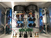
I figured I would try the twisting as best as I could with the existing wiring since it was the simplest way to see if there was any benefit without having to do any major re-wiring. I attached a pic showing the difference between the two channels.
The difference was remarkable!
On the bench with my test speakers I couldn’t hear any noise with my ear against the speakers.
I decided to give it a try in my system again.
It is very quiet now. There is still some residual noise that I can hear when I am close to the speaker.
I played with a sheet of shielding material in between the signal wiring and the power supply and there seemed to be a slight reduction depending on where I held it.
To put things in perspective I fired up one of my F2J monoblocks on the other channel to compare.
I had always considered the F2Js dead silent.
I have to almost have my ear in contact with the whizzer of my Lii Crystal 10s for noise to register from the F2J. Its a very very faint buzzing.
I would say the channel with twisted wiring on the new amp is a few orders of magnitude higher in terms of noise level now.
I guess I’m wondering how far I should go in terms of expectations and chasing this to reduce noise by modifying my wiring further.
I’m going to shorten the input wires as much as I can.
I’m wondering whether extending the binding post wiring so it can be twisted further is a good idea.
Regarding the power supply wiring from the cap bank, is there a better way to route things and should I extend any of the wiring to facilitate that?
I looked over the pdf that was linked. A good portion was too dense for me. Luckily toward the end there was the “How to apply in the real world” sections.
I figured I would try the twisting as best as I could with the existing wiring since it was the simplest way to see if there was any benefit without having to do any major re-wiring. I attached a pic showing the difference between the two channels.
The difference was remarkable!
On the bench with my test speakers I couldn’t hear any noise with my ear against the speakers.
I decided to give it a try in my system again.
It is very quiet now. There is still some residual noise that I can hear when I am close to the speaker.
I played with a sheet of shielding material in between the signal wiring and the power supply and there seemed to be a slight reduction depending on where I held it.
To put things in perspective I fired up one of my F2J monoblocks on the other channel to compare.
I had always considered the F2Js dead silent.
I have to almost have my ear in contact with the whizzer of my Lii Crystal 10s for noise to register from the F2J. Its a very very faint buzzing.
I would say the channel with twisted wiring on the new amp is a few orders of magnitude higher in terms of noise level now.
I guess I’m wondering how far I should go in terms of expectations and chasing this to reduce noise by modifying my wiring further.
I’m going to shorten the input wires as much as I can.
I’m wondering whether extending the binding post wiring so it can be twisted further is a good idea.
Regarding the power supply wiring from the cap bank, is there a better way to route things and should I extend any of the wiring to facilitate that?
Attachments
It's great that you are getting results.
I would suggest lengthening the Gnd wire from the PS board and twist it with the V+ and V- all the way to the amplifier board V+ V- connection point and then take the wire to the Gnd point of the amplifier board. Do the same with the Speaker Gnd, twist with Speaker+ all the way to the amplifier board and then take the Gnd to the Gnd point.
Another place to improve would be at the IEC. Take a twisted pair of Hot and Neutral to each fuse, connect the Hot to the fuse, and then continue the twisted pair onward to the each channel's board.
Looking at your twisted input wires, I would twist them much tighter.
Last edited:
well, I'm absent one nigt and you Boyz did (almost) everything without me
I need to be absent more often, obviously
🙂
I need to be absent more often, obviously
🙂
BTW, what do you guys use for wiring? I like teflon stuff but they are really hard to twist together.
For input wiring the twisted pairs from CAT6 cables work great and are 'pre-twisted'. 🙂
Thanks,
Dennis
For input wiring the twisted pairs from CAT6 cables work great and are 'pre-twisted'. 🙂
Thanks,
Dennis
Basic 20 gauge stranded copper for V+ V-BTW, what do you guys use for wiring? I like teflon stuff but they are really hard to twist together.
For input wiring the twisted pairs from CAT6 cables work great and are 'pre-twisted'. 🙂
Thanks,
Dennis
Basic 16 gauge stranded for AC Mains and outputs
CAT 5 or CAT 6 for inputs or wire ZM recommended. It's fiddly, but it makes me feel like a true DIYer when I don't totally mangle it. 😀
https://www.digikey.com/en/products...KMAExfzI6lrtteti30qOxhljUWeTRUvhoC4iMQAvD_BwE
Enough to last most people a lifetime.
I’m in the same boat with IAIMH
I think I used a slightly heavier gauge for the binding posts. Most times the PCB design dictates what I use as long as the gauge seems reasonable for its purpose.
The CAT cable seems like a no brainer and convenient.
There have been a few cases where shielding wire was necessary for me in sensitive cases like phono amps
I tried some surplus “mil-spec” teflon coated wire on a few projects.
I found it to be more difficult to solder as well as manipulate and wasn’t worth the hassle for me.
Just wanted to mention I also rotated the transformer so the wire outlet faced down in the last round of modifications.
I also forgot to post a pic of the AC wiring.
Most of what I do is “Monkey See Monkey Do” from looking over ZMs build documentation on his blog.
Attachments
I think 20 gauge for V+ V- Gnd is a bit light. For most solid state amplifiers V+ V- is lower than AC, so DC current is much higher than AC current. Current determines wire size.Basic 20 gauge stranded copper for V+ V-
Basic 16 gauge stranded for AC Mains and outputs
CAT 5 or CAT 6 for inputs or wire ZM recommended. It's fiddly, but it makes me feel like a true DIYer when I don't totally mangle it. 😀
I usually use 16 gauge for V+, V-, and Ground. I also use 16 gauge for AC although based on current the AC wires may be smaller than the DC wires.
Great call out, Ben. I should have also mentioned that so as to not confuse anyone. If I could add one thing though... it is not only current dependent, but length dependent, I believe. With the wire lengths and amperages in my FW-based amps, 20 gauge is OK for the DC supplies. However, I have occasionally used 16 and even 12 in one case just to have a great deal of extra margin and to flex on lesser DIYers. 
Going through my case re-wiring and twisting.
It appears I wired everything with 16 gauge except the ground strap running to my IEC which is 14 gauge…and of course the signal input is CAT wire.
Strangely enough, the Lindberg transformers I’m using came from the manufacturer with 16 gauge secondary leads but only 20 gauge primary leads.
It appears I wired everything with 16 gauge except the ground strap running to my IEC which is 14 gauge…and of course the signal input is CAT wire.
Strangely enough, the Lindberg transformers I’m using came from the manufacturer with 16 gauge secondary leads but only 20 gauge primary leads.
In post #711 I did a poor job of explaining but I tried to say that wire size is determined by the current carried.
Ignoring small losses here and there, power is conserved such that the input power and the output power of the transformer (and power supply) is the same. Power = Voltage x current, so for equal power in and out, the current in the primary windings at 120V is lower than the current in the secondary windings at 18V. Thus the primary leads are smaller than the secondary leads.
Ignoring small losses here and there, power is conserved such that the input power and the output power of the transformer (and power supply) is the same. Power = Voltage x current, so for equal power in and out, the current in the primary windings at 120V is lower than the current in the secondary windings at 18V. Thus the primary leads are smaller than the secondary leads.
Hi Ben - I think you did an excellent job as always in your explanations. However, there are a few separate, but related situations. Note, some of this is also just me thinking it through. I don't assert to be correct, below is simply my understanding and adding a bit of clarity (when I actually use logic vs. just picking something pretty). If I'm incorrect, then I always enjoy learning, particularly if I've been using an unsafe practice.
You explanation for why step-down transformer primaries are generally a smaller diameter than the secondaries is spot on, IMO.
You also mentioned DC current being higher than AC current within a typical amplifier of this type and class. Understood.
I was simply noting in reply to your statement (after quoting mine) that 20 AWG may be a bit light for the DC supplies. Your reasoning is solid and correct, IMO. I felt that it left out a key element though. I wanted to call out that not only is AWG choice commonly made by current, but also by the length of the run. In my case, the lengths of my DC supply lines for FW-based amps with 24VDC supplies are usually well under 12", and the current is well under 3A. 20 AWG is sufficient for that application for less than a 1% drop, keeping heat in check etc. IMO, it is not a "bit light" for those applications, two of which were/are my Babel J2s. Others (and I) may use heavier wires for engineering reasons or just 'because'.
I hope that clarifies.
I apologize for my poor choice of words as I did not mean to imply that your wiring was inadequate and not capable of carrying the load.
The point that I was trying to make but totally missed doing was that the 20 gauge was "a bit light" in the context of the other wires' gauges when comparing current capacity to current carried.
My bad. 😳
The point that I was trying to make but totally missed doing was that the 20 gauge was "a bit light" in the context of the other wires' gauges when comparing current capacity to current carried.
My bad. 😳
I always appreciate input and guidance. That's why I wanted to be really sure I had not missed anything.
No bad on your part at all. I completely understand your point now, and it's valid. Thanks as always for taking the time once again. 😀
No bad on your part at all. I completely understand your point now, and it's valid. Thanks as always for taking the time once again. 😀
I’m finally listening
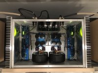
I went back in after having twisted the supply wiring on the first channel between the transformers, bridges, cap banks and amp boards.
I extended the binding post wiring so it could be twisted further. I also shortened the input wires so I could just get them connected.
At that point I was wringing my hands over the task of having to pull all of the supply out again to modify and twist the AC wiring as well as extend the ground from the cap bank to the amp board so it could be twisted more.
I decided to give it a listen and discovered I was just barely able to hear the slightest level higher noise than I could hear from my F2Js.
I did some more hand wringing and wrestling with my OCD while I applied the wiring modifications I had already done to the second channel.
Finally, I decided it might be less painful to try making a shield to encase the AC wiring…or at least it seemed less offensive than having to pull everything out again and curse over desoldering one more time. Then I could decide if the cap bank ground needed work.
It turned into a bit of a struggle to fabricate and fit something, but in the end the results were phenomenal.
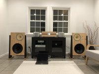
This amp now surpasses my F2J monoblocks. It is so quiet that I easily end up hitting my ear against the speaker cone before any noise registers in my hearing.
I’ve been enjoying music as it came up to temp over the last hour or so.
I’m looking forward to spending some time with it and trying some comparisons with the F2Js, VFET, ACAs and few others I have lying around.
Thanks you all…especially ZM…for helping to get me here!
I took a few pics while having my first listen.
I went back in after having twisted the supply wiring on the first channel between the transformers, bridges, cap banks and amp boards.
I extended the binding post wiring so it could be twisted further. I also shortened the input wires so I could just get them connected.
At that point I was wringing my hands over the task of having to pull all of the supply out again to modify and twist the AC wiring as well as extend the ground from the cap bank to the amp board so it could be twisted more.
I decided to give it a listen and discovered I was just barely able to hear the slightest level higher noise than I could hear from my F2Js.
I did some more hand wringing and wrestling with my OCD while I applied the wiring modifications I had already done to the second channel.
Finally, I decided it might be less painful to try making a shield to encase the AC wiring…or at least it seemed less offensive than having to pull everything out again and curse over desoldering one more time. Then I could decide if the cap bank ground needed work.
It turned into a bit of a struggle to fabricate and fit something, but in the end the results were phenomenal.
This amp now surpasses my F2J monoblocks. It is so quiet that I easily end up hitting my ear against the speaker cone before any noise registers in my hearing.
I’ve been enjoying music as it came up to temp over the last hour or so.
I’m looking forward to spending some time with it and trying some comparisons with the F2Js, VFET, ACAs and few others I have lying around.
Thanks you all…especially ZM…for helping to get me here!
I took a few pics while having my first listen.
Attachments
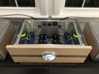
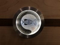

Wow!, Looks great Chrome... I love the amp design and the ZM Babelfish J2 logo.
ZM might have to get that logo on the next batch of PCBs.
ZM might have to get that logo on the next batch of PCBs.

- Home
- Amplifiers
- Pass Labs
- Babelfish ᄅſ....or FW J2 on Steroids .... or Not your Father's J2!