Maybe try some Mur820 diodes or playing with snubber cap values in your current boards? LT4320 active rectifiers also seem to be gaining popularity around here as well.
LT4320 based active rectifier
But looking at your wiring I'm not sure the rectifiers are your issue. Could still be a potential grounding issue. Your green power ground wires look pretty long. Maybe try shortening and re-routing. Or even running power ground from the board directly to your star ground? Thoughts ZM?
Or go true dual mono. The only way to be sure. 😉
I’m using those Field effect diodes right now, and definitely liked them over GBPC monoliths (although I wasn’t measuring anything at that point.). I just went from 2 trafos to this one biggin. Didn’t really impact measurements or sound, though I also redid some other wiring this go around. I like your ground suggestion - might play with that. I debated on running the ground with the rails as much as possible, or going more direct.
TBH, I think I was a happier audiophile when I wasn’t measuring stuff (Albeit less informed). 🙂
TBH, I think I was a happier audiophile when I wasn’t measuring stuff (Albeit less informed). 🙂

Probably right. ZM - thoughts on taking amp ground to star? Is the goal the shortest distance above all else?
codyt, is the 60hz audible or just on the scope?
If not audible I may never want to measure my amps either!
If not audible I may never want to measure my amps either!
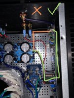
Kinda interesting... I swapped my existing ground routing (green in pic) for a much shorter and more direct path (orange in pic). With the longer route I’m able to clear any overlap of the output and completely remove audible hum from the speaker. With the more direct path, it significantly increased hum. My conclusion is that the shorter path actually creates a larger loop area and interacts with the output. The longer route avoids the output wiring and reduces the loop area. Or at least that’s how I understand it.
I only share this because it’s counter-intuitive to my small, novice brain and I found the result surprising.
I only share this because it’s counter-intuitive to my small, novice brain and I found the result surprising.
Attachments
You've increased the loop area by separating the ground wire from the V+ and V-. On the same subject you have a large loop in your speaker out and ground wires.
Another thing I noticed was the power transformer orientation. My experience with Antek transformers is that it matters. Rotate the transformer to find the position of least noise. My experience is to have the transformer oriented such that the wires leave the transformer at six and twelve o'clock positions for least noise.
Another thing I noticed was the power transformer orientation. My experience with Antek transformers is that it matters. Rotate the transformer to find the position of least noise. My experience is to have the transformer oriented such that the wires leave the transformer at six and twelve o'clock positions for least noise.
That’s good feedback - thanks! As far as the speaker out and ground - maybe taking speaker ground direct from PSU would take care of that?
I would twist the two wires together at the back panel and take that to the speaker out on the circuit board, and then continue the ground wire to the ground point on the board, similar to your V+,V-,G.
if you're not in the mood, first day rotate your self around amplifier


Regarding component substitution:
In the CCS for Opto, can I use a 47uF 35V cap in place of the 33uF/50V?
Same for C101 in the LTP CCS - 47uF/35V in place of 33uF/50V?
In Opto Bias the 470uF/16V cap can I use 1000uF here instead?
In the CCS for Opto, can I use a 47uF 35V cap in place of the 33uF/50V?
Same for C101 in the LTP CCS - 47uF/35V in place of 33uF/50V?
In Opto Bias the 470uF/16V cap can I use 1000uF here instead?
Last edited:
Double checking posts #322 and #323 - if we have the 4 JFETS pre-populated by you with SMD 2SK2145 in J101-J104 we do NOT populate R110 and R114 is that correct?
do not use these resistors
so , no R114, no R110
- Home
- Amplifiers
- Pass Labs
- Babelfish ᄅſ....or FW J2 on Steroids .... or Not your Father's J2!